Archives: Products

PCAN-LIN

PCAN-LIN

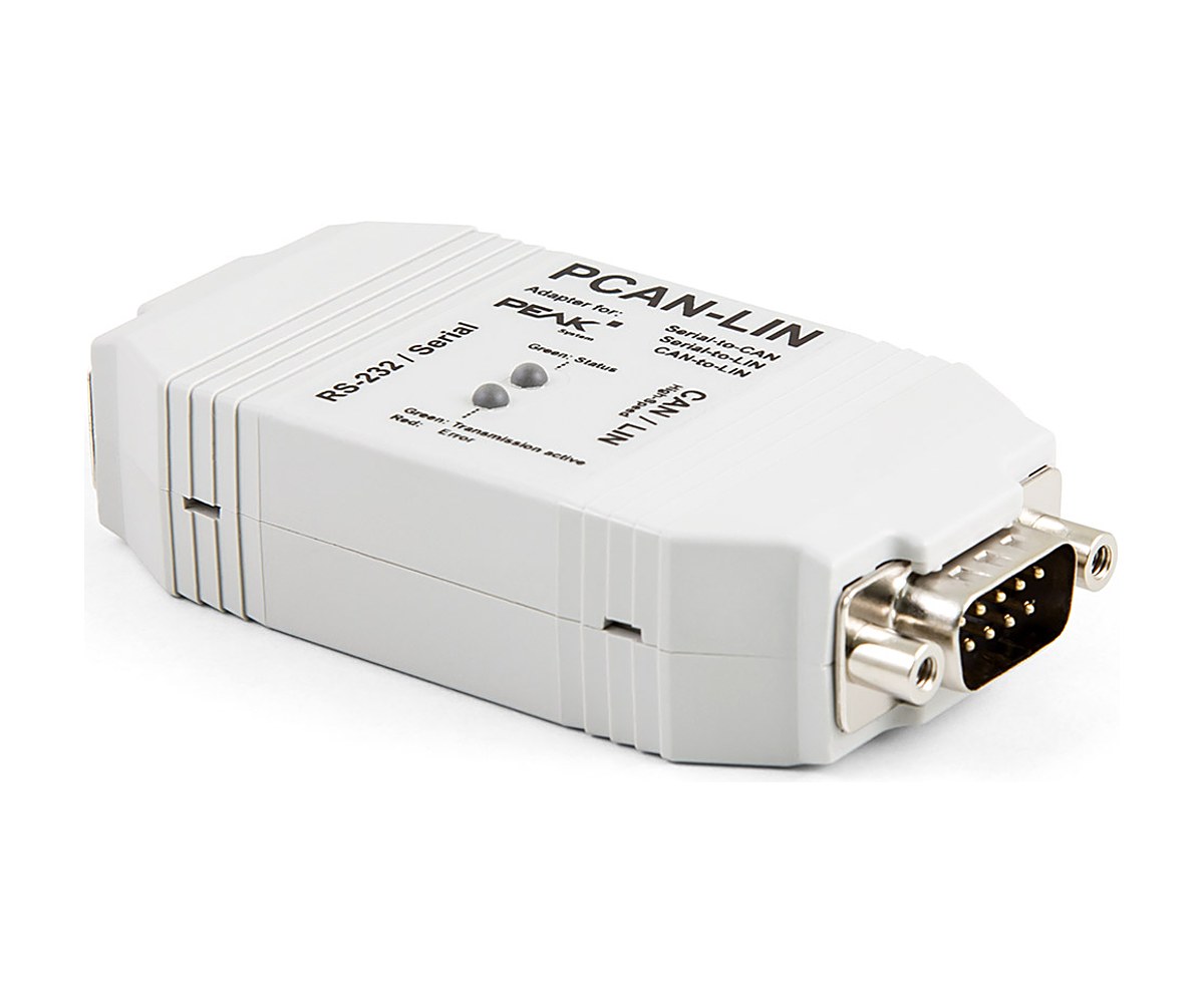
Exchange data between LIN, CAN and RS-232 nodes

PCAN-LIN is a gateway module in a plastic casing that lets LIN, CAN and serial devices talk to each other. Its firmware routes data between RS-232 and LIN, CAN and LIN, and RS-232 and CAN, in both directions.

With the PCAN-LIN Config software you choose the mode. As LIN master, for example, it polls LIN nodes and passes their data to CAN, to the serial port or to both, optionally with an ID offset. It can also act as a LIN slave or simulate slaves whose data you change over CAN.

Highlights

  • Gateway between RS-232, CAN and LIN
  • LIN master or slave, LIN 1.x and 2.x frames
  • LIN slave simulation, data changed via CAN
  • LIN ID scheduler list
  • Opto-decoupled version with 1 kV isolation
  • 9 to 30 V supply, -40 to 85 C

Versions

  • IPEH-002025: PCAN-LIN High-speed CAN
  • IPEH-002029: PCAN-LIN High-speed CAN opto-decoupled
  • The Low-speed CAN version (IPEH-002028) is no longer made

Key Specifications

SpecValue
Order numbersIPEH-002025, IPEH-002029 (opto-decoupled)
CANHigh-speed CAN (ISO 11898-2), CAN 2.0 A/B, up to 1 Mbit/s
LIN1 to 20 kbit/s, LIN 1.x and 2.x, master or slave
RoutingRS-232 to LIN, CAN to LIN, RS-232 to CAN (limited bandwidth)
IsolationUp to 1 kV between RS-232 and CAN/LIN (opto-decoupled version)
Supply9 to 30 V
Operating temperature-40 to 85 C

In the Box

  • PCAN-LIN in plastic casing (version as ordered)
  • PCAN-LIN Config, configuration and monitoring tool for Windows 11 (x64/ARM64) and 10 (x64)
  • Manual (PDF)

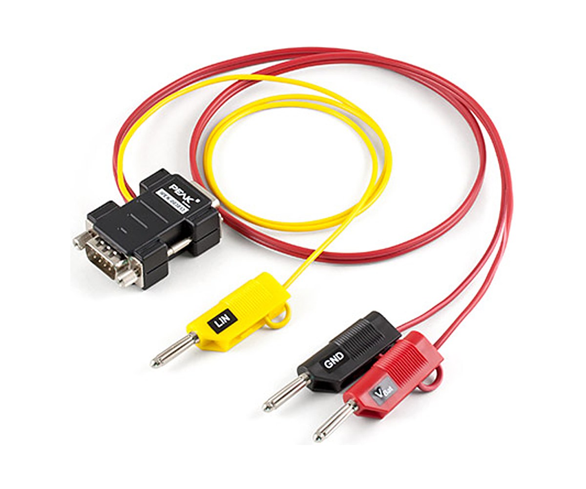
To wire the module, see the LIN Connection Cable for PCAN-LIN. For LIN on a PC, see the PLIN-USB.

For quantities, lead time or a quote, contact Pertech.

PCAN-Router

PCAN-Router

A dual-channel CAN module you program in C or C++

PCAN-Router sits between two classic CAN buses and does whatever its firmware tells it: pass messages through, filter them, change their content, or evaluate them. It is built around an NXP LPC21 series microcontroller (16/32-bit ARM) and comes in an aluminium profile casing, with two D-Sub connectors or a single screw-terminal strip.

Out of the box it runs a standard firmware that forwards every message unchanged between the two channels at 500 kbit/s, and the source of that firmware is supplied as a starting point. Your own firmware is written with the Windows development package (GCC ARM Embedded plus examples) and loaded into the module over CAN with PEAK-Flash.

Highlights

  • 2 High-speed CAN channels, 40 kbit/s to 1 Mbit/s
  • Freely programmable, NXP LPC21 (ARM) microcontroller
  • Standard firmware with 1:1 forwarding, source included
  • Firmware upload over CAN
  • D-Sub, screw-terminal or opto-decoupled versions
  • 8 to 30 V supply, -40 to 85 C

Versions

  • IPEH-002210: PCAN-Router with D-Sub connectors
  • IPEH-002210-P: PCAN-Router with Phoenix screw-terminal connector
  • IPEH-002211: PCAN-Router with D-Sub connectors, opto-decoupled (galvanic isolation on CAN 2)

Software

  • Standard firmware installed on delivery, source code included
  • Windows development package with GCC ARM Embedded and programming examples
  • PEAK-Flash for Windows 11 (x64/ARM64) and 10 (x64)
  • Loading firmware over CAN needs a PEAK CAN interface

Key Specifications

SpecValue
Order numbersIPEH-002210, IPEH-002210-P, IPEH-002211
CAN2 x High-speed CAN (ISO 11898-2), CAN 2.0 A/B
Bit rates40 kbit/s to 1 Mbit/s
MicrocontrollerNXP LPC21 series (16/32-bit ARM), 32 kbyte EEPROM
Connectors2 x D-Sub 9-pin, or 1 x 10-pole Phoenix screw-terminal strip
Extra I/OOne digital input (IPEH-002210 and IPEH-002211 only)
StatusTwo 2-color LEDs
CasingAluminium profile, DIN rail fixing optional
Supply8 to 30 V
Operating temperature-40 to 85 C

In the Box

  • PCAN-Router in aluminium casing (version as ordered)
  • Phoenix mating connector (IPEH-002210-P only)
  • Windows development package with GCC ARM Embedded and examples
  • PEAK-Flash for Windows
  • Manual (PDF)

For CAN FD, see the PCAN-Router FD; for a DIN rail housing, the PCAN-Router DR; for more channels, the PCAN-Router Pro.

For quantities, lead time or a quote, contact Pertech.

PCAN-Router FD

PCAN-Router FD

Two programmable CAN FD channels that bridge CAN and CAN FD

PCAN-Router FD connects two CAN FD or classic CAN buses and routes data between them under control of your own firmware. A typical job is converting between CAN 2.0 and CAN FD, so that a new CAN FD device can work inside an existing classic network. The processor is an NXP LPC4078 (Arm Cortex-M4 with FPU, 120 MHz), and the module comes in an aluminium profile casing with D-Sub or screw-terminal connections.

It ships with a standard firmware whose source code is included. Custom firmware is built in C or C++ with the Windows development package and GCC ARM Embedded, then loaded over CAN. An RS-232 port, a digital output and digital inputs give the firmware a few extra signals to work with.

Highlights

  • 2 CAN FD channels, data rates up to 12 Mbit/s, ISO and Non-ISO
  • CAN to CAN FD conversion in either direction
  • Freely programmable in C/C++, Arm Cortex-M4F
  • RS-232 port plus digital input and output
  • Termination per channel by solder jumper
  • 8 to 30 V supply, -40 to 85 C

Versions

  • IPEH-002214: PCAN-Router FD with D-Sub connectors
  • IPEH-002215: PCAN-Router FD with Phoenix screw-terminal connector

Software

  • Standard firmware installed on delivery, source code included
  • Windows development package with GCC ARM Embedded and programming examples
  • PEAK-Flash for Windows 11 (x64/ARM64) and 10 (x64)
  • Loading firmware over CAN needs a PEAK CAN interface

Key Specifications

SpecValue
Order numbersIPEH-002214 (D-Sub), IPEH-002215 (Phoenix)
CAN2 x High-speed CAN (ISO 11898-2), CAN 2.0 A/B and CAN FD, ISO and Non-ISO
Bit ratesCAN 40 kbit/s to 1 Mbit/s; CAN FD data 40 kbit/s to 12 Mbit/s
TransceiverNXP TJA1043T with wake-up
MicrocontrollerNXP LPC4078 (Arm Cortex-M4 with FPU, 120 MHz)
Memory4 kByte on-chip EEPROM, 8 MByte SPI flash
I/ORS-232; 1 digital input; 1 low-side digital output (max. 600 mA); 2 more inputs usable in place of RS-232
Connectors2 x D-Sub 9-pin, or 1 x 10-pole Phoenix screw-terminal strip
Supply8 to 30 V
Operating temperature-40 to 85 C

In the Box

  • PCAN-Router FD in aluminium casing (version as ordered)
  • Phoenix mating connector (IPEH-002215 only)
  • Windows development package with GCC ARM Embedded and examples
  • PEAK-Flash for Windows
  • Manual (PDF)

For more CAN FD channels, see the PCAN-Router Pro FD; for classic CAN only, the PCAN-Router.

For quantities, lead time or a quote, contact Pertech.

PCAN-Router DR

PCAN-Router DR

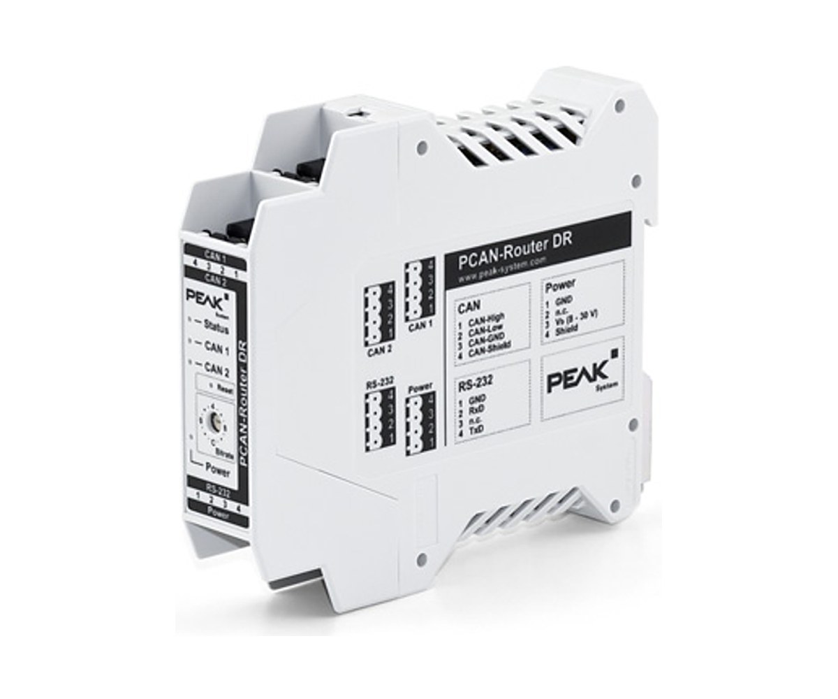
Programmable two-channel CAN router on a DIN rail, with 5 kV isolation

PCAN-Router DR has two High-speed CAN channels and, out of the box, forwards all traffic 1:1 in both directions between them. You set the bit rate with a rotary switch on the front. Its DIN rail casing and wide temperature range make it a fit for control cabinets.

CAN 1 is isolated up to 5 kV from the rest of the device, in line with IEC 60601-1, and the other ports are isolated by at least 500 V. Like the aluminium-cased PCAN-Router, it is freely programmable: a development package with GCC and examples is included, and firmware is loaded over CAN.

Highlights

  • Two High-speed CAN channels, 5 kbit/s to 1 Mbit/s
  • Bit rate set by rotary switch
  • CAN 1 isolated up to 5 kV (IEC 60601-1)
  • Freely programmable, NXP LPC21 ARM microcontroller
  • Switchable termination per channel
  • DIN rail, 22.5 mm wide, -40 to 85 C

Software

  • Windows development package with GCC ARM Embedded and programming examples
  • PEAK-Flash for Windows 11 (x64/ARM64) and 10 (x64)
  • Loading firmware over CAN needs a PEAK CAN interface

Key Specifications

SpecValue
Order numberIPEH-002213
MicrocontrollerNXP LPC21 series (16/32-bit ARM), 32 kbyte EEPROM
CAN2 x High-speed CAN (ISO 11898-2), CAN 2.0 A/B, 5 kbit/s to 1 Mbit/s
TransceiverNXP PCA82C251
IsolationCAN 1 up to 5 kV; CAN 2 and RS-232 500 V
ConnectionsPhoenix 4-pole screw terminals for CAN, RS-232 and power
Supply8 to 30 V
Operating temperature-40 to 85 C

In the Box

  • PCAN-Router DR in DIN rail plastic casing
  • Mating connectors for both CAN channels, RS-232 and power
  • Windows development package with GCC ARM Embedded and examples
  • PEAK-Flash for Windows
  • Manual (PDF)

The same function in an aluminium casing is the PCAN-Router; for CAN FD, see the PCAN-Router FD. A PCAN-USB loads the firmware.

For quantities, lead time or a quote, contact Pertech.

PCAN-Router Pro

PCAN-Router Pro

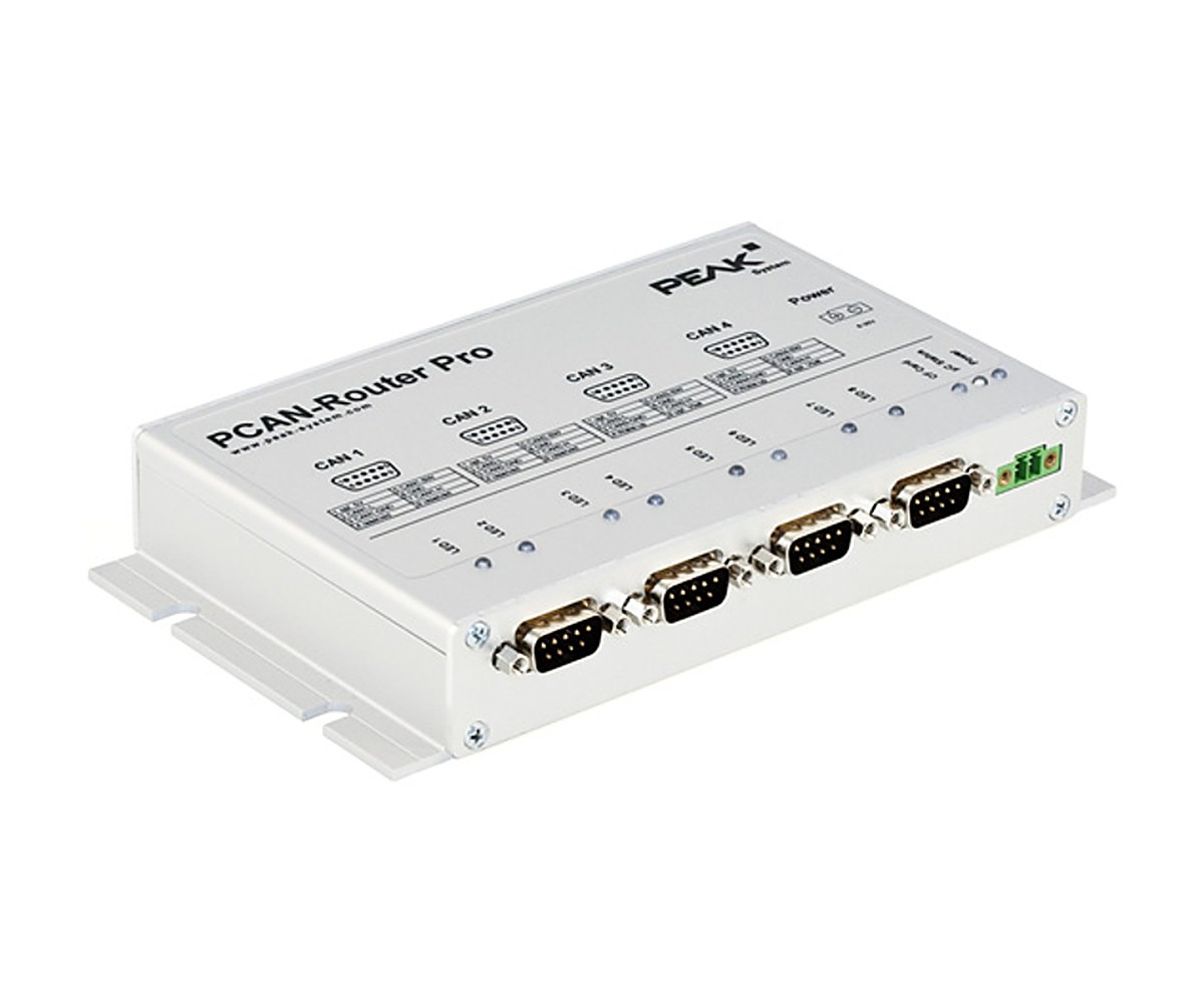
Four-channel CAN router with logging, set up without writing code

PCAN-Router Pro joins the traffic of four High-speed CAN buses. You configure it over CAN with the supplied PPCAN-Editor 2: beyond plain forwarding, function blocks let you filter, process and manipulate the data.

A virtual fifth CAN channel records all traffic to a CompactFlash card. If the standard firmware is not enough, you can write your own C or C++ firmware for the NXP LPC2294 with the included GNU development package and load it over CAN.

Highlights

  • 4 High-speed CAN channels, 40 kbit/s to 1 Mbit/s
  • Configured with PPCAN-Editor 2 function blocks
  • Logging to CompactFlash card
  • Custom firmware option on the LPC2294
  • Exchangeable transceiver modules per channel
  • Real-time clock with wake-up, -40 to 85 C

Software

  • PPCAN-Editor 2 for Windows: configuration
  • PEAK-Converter for Windows: converts log data
  • Windows development package with GCC ARM Embedded and examples, plus PEAK-Flash
  • Configuration and firmware loading over CAN need a PEAK CAN interface
  • PEAK notes that only units with serial number 100 or higher accept custom firmware

Key Specifications

SpecValue
Order numberIPEH-002212
CAN4 x High-speed CAN (ISO 11898-2), CAN 2.0 A/B, 40 kbit/s to 1 Mbit/s
TransceiverNXP TJA1041 with wake-up; alternative modules available
ConnectorsD-Sub 9-pin (CiA 106), switchable termination per channel
MicrocontrollerNXP LPC2294
LoggingCompactFlash card slot (industrial card of at least 1 GB included)
CasingAluminium with flange; DIN rail fixing on request
Supply8 to 27 V, overvoltage and reverse polarity protected
Operating temperature-40 to 85 C

In the Box

  • PCAN-Router Pro in aluminium casing with power mating connector
  • Industrial CompactFlash card (min. 1 GB)
  • PPCAN-Editor 2 and PEAK-Converter for Windows
  • Windows development package with GCC ARM Embedded and examples
  • PEAK-Flash for Windows
  • Manual (PDF)

For CAN FD and six channels, see the PCAN-Router Pro FD.

For quantities, lead time or a quote, contact Pertech.

PCAN-Router Pro FD

PCAN-Router Pro FD

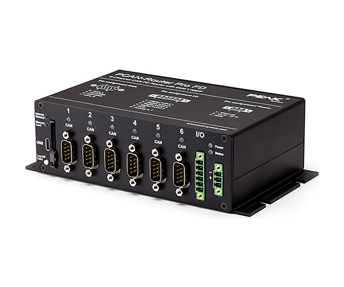
Six CAN FD channels, I/O and a 16 GB logger in one programmable router

PCAN-Router Pro FD links six CAN FD and classic CAN buses. It can convert between CAN and CAN FD, which lets new CAN FD devices join an existing CAN 2.0 network, and it suits managing, monitoring and controlling data on test benches and production lines.

It ships with firmware for configurable CAN and CAN FD logging to 16 GB of internal memory or an SD card, read out over USB. For your own behaviour, write C or C++ firmware with the included GNU development package and load it over CAN. It also has an analog input and four digital I/Os.

Highlights

  • 6 CAN FD channels, up to 12 Mbit/s data rate
  • Logging to 16 GB pSLC eMMC plus SD card
  • Freely programmable in C/C++, Arm Cortex-M7
  • 4 digital I/Os and 1 analog input (0 to 32 V)
  • Exchangeable transceiver modules per channel
  • Version with 100 Mbit/s Ethernet

Versions

  • IPEH-002220: PCAN-Router Pro FD
  • IPEH-002222: PCAN-Router Pro FD with Ethernet interface (RJ-45, up to 100 Mbit/s)

Software

  • Recording firmware installed on delivery
  • Windows development package with GCC ARM Embedded and programming examples
  • PEAK-Flash and PEAK-Converter for Windows
  • Loading firmware over CAN needs a PEAK CAN interface

Key Specifications

SpecValue
Order numbersIPEH-002220, IPEH-002222 (with Ethernet)
CAN6 x High-speed CAN (ISO 11898-2), CAN 2.0 A/B and CAN FD, ISO and Non-ISO
Bit ratesCAN 40 kbit/s to 1 Mbit/s; CAN FD data 40 kbit/s to 12 Mbit/s
TransceiverNXP TJA1043 with wake-up; alternative modules available
MicrocontrollerSTM32F765NIH6 (Arm Cortex-M7), plus 32 MB SDRAM
Memory16 GB pSLC eMMC, SD card slot
I/O2 high-side and 2 low-side digital I/Os, 1 analog input 0 to 32 V
Supply8 to 32 V, overvoltage and reverse polarity protected
Operating temperature-40 to 85 C

In the Box

  • PCAN-Router Pro FD in aluminium casing with mating connectors for I/O and power
  • USB cable
  • RJ-45 patch cord, 2 m (IPEH-002222 only)
  • Windows development package with GCC ARM Embedded and examples
  • PEAK-Flash and PEAK-Converter for Windows
  • Manual (PDF)

For two channels, see the PCAN-Router FD; the classic CAN model is the PCAN-Router Pro.

For quantities, lead time or a quote, contact Pertech.

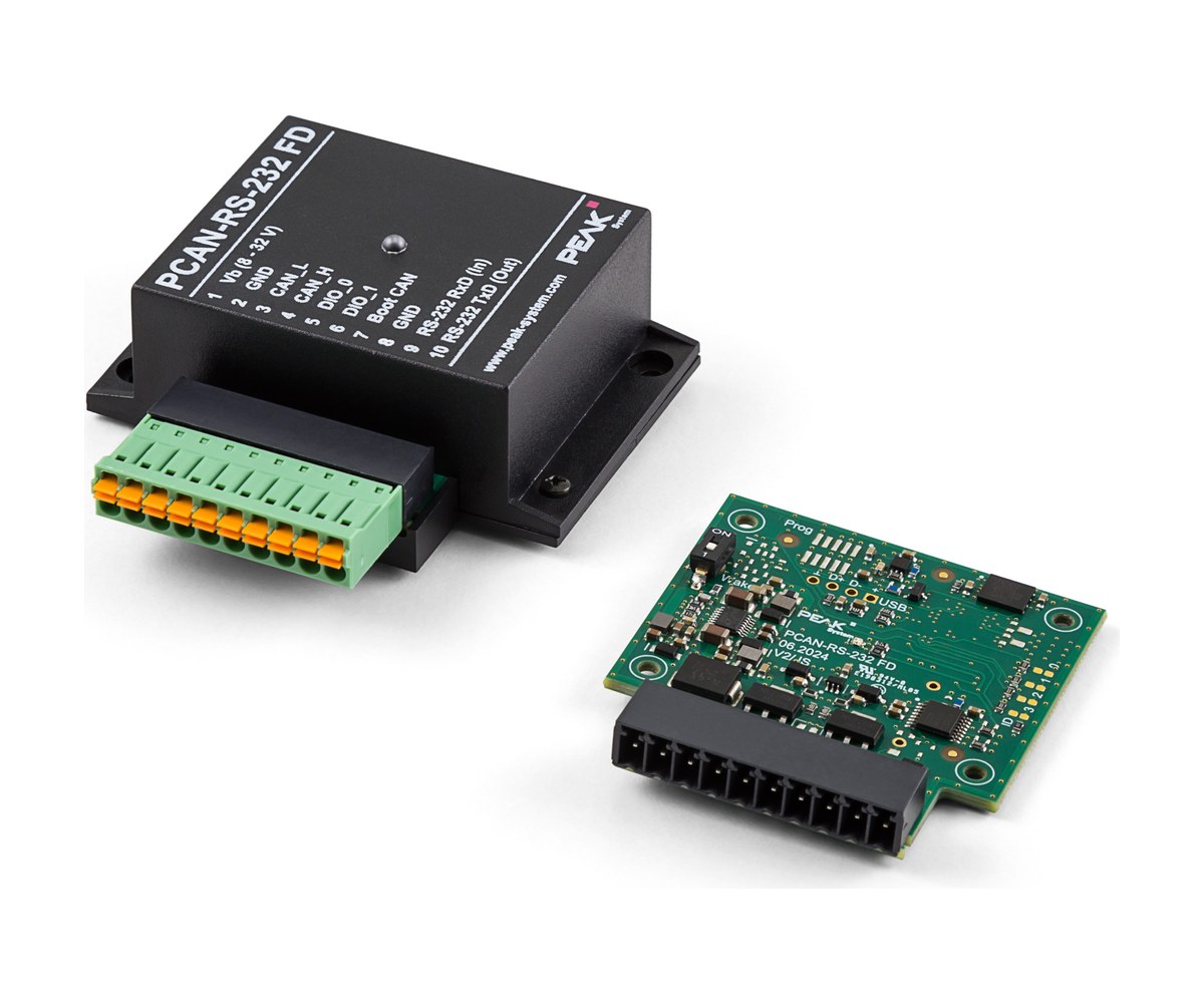
PCAN-RS-232 FD

PCAN-RS-232 FD

Bring serial devices onto a CAN FD bus with a programmable converter

PCAN-RS-232 FD converts traffic between an RS-232 port and a CAN FD connection, so machines, PLCs, sensors and actuators with a serial interface can join a classic CAN or CAN FD network.

On delivery its firmware routes CAN FD to RS-232 and back, and you set up the transfer and the hardware with serial commands; the source code of that firmware is included as an example. For other behaviour, write your own C or C++ firmware with the included GNU package and load it over CAN.

Highlights

  • RS-232 to CAN FD and back
  • Standard firmware with serial command setup
  • Freely programmable, Arm Cortex-M4
  • RS-232 up to 460,800 bit/s
  • 2 digital I/Os
  • 8 to 32 V supply, -40 to 85 C

Software

  • Standard CAN FD to RS-232 firmware, with source code as an example
  • Windows development package with GCC ARM Embedded and examples
  • PEAK-Flash for Windows 11 (x64/ARM64) and 10 (x64)
  • Loading firmware over CAN needs a PEAK CAN interface

Key Specifications

SpecValue
Order numberIPEH-003120
MicrocontrollerNXP LPC54618 (Arm Cortex-M4), 8 MB QSPI flash
CANHigh-speed CAN (ISO 11898-2), CAN 2.0 A/B and CAN FD
Bit ratesCAN 40 kbit/s to 1 Mbit/s; CAN FD data 40 kbit/s to 10 Mbit/s
CAN transceiverNXP TJA1043 with wake-up
RS-232TI TRSF3221E, up to 460,800 bit/s
Connection10-pole Phoenix terminal strip
Supply8 to 32 V
Operating temperature-40 to 85 C

In the Box

  • PCAN-RS-232 FD in plastic casing with mating connector
  • Windows development package with GCC ARM Embedded and examples
  • PEAK-Flash for Windows
  • Manual (PDF)

The classic CAN version is the PCAN-RS-232. A PCAN-USB FD can load the firmware.

For quantities, lead time or a quote, contact Pertech.

PCAN-RS-232

Special price: last units in stock

This model is discontinued by the manufacturer; Pertech still has a few units. Contact us for a quote. For new designs, see the PCAN-RS-232 FD.

PCAN-RS-232

Legacy programmable CAN to RS-232 converter

PCAN-RS-232 links a High-speed CAN bus with a serial RS-232 device. Its NXP LPC21 series microcontroller (16/32-bit ARM) runs a standard firmware that passes data both ways, and both the transfer and the hardware are set up with serial commands.

The module is also freely programmable: firmware written in C or C++ with the supplied GCC-based package is loaded over CAN. PEAK no longer builds it. Remaining units may be available on request, and new designs should use the PCAN-RS-232 FD.

Key Specifications

SpecValue
StatusDiscontinued; successor PCAN-RS-232 FD
CANHigh-speed CAN (ISO 11898-2), CAN 2.0 A/B, 40 kbit/s to 1 Mbit/s
RS-232Up to 115,200 bit/s
MicrocontrollerNXP LPC21 series (16/32-bit ARM), 32 KB EEPROM
I/O1 digital input, 1 digital output (low-active)
Connector10-pole Phoenix terminal strip
Supply8 to 30 V
Operating temperature-40 to 85 C

In the Box

  • PCAN-RS-232 in plastic casing, with 10-pole mating connector
  • Windows development package with GCC ARM Embedded and examples
  • PEAK-Flash for firmware updates
  • Manual (PDF)

For new projects, see the PCAN-RS-232 FD; to load firmware you need a PEAK CAN interface such as the PCAN-USB FD.

For remaining stock, the successor or a quote, contact Pertech.

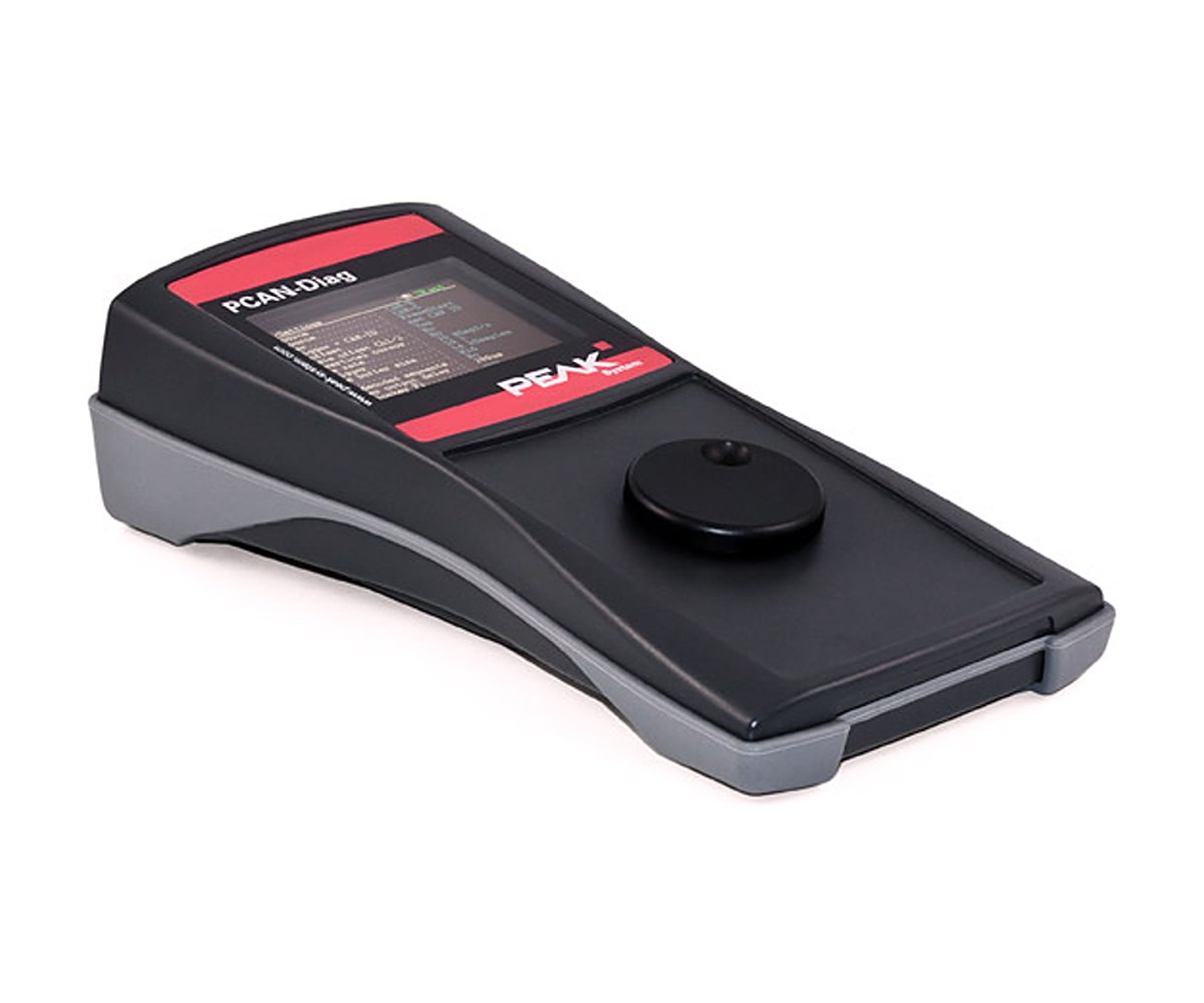
PCAN-Diag 2

PCAN-Diag 2

Handheld CAN bus tester with a built-in two-channel scope

PCAN-Diag 2 is a handheld unit for checking a High-speed CAN bus in the field. It finds the bit rate, measures bus load and termination, reads the voltage on every pin of the D-Sub connector, and receives and transmits CAN frames.

A two-channel oscilloscope shows CAN-High, CAN-Low and their difference, and decodes frames straight from the analog trace so you can see where a frame breaks. Traffic can be recorded to the internal memory card and played back later. You work it with a single push dial.

Highlights

  • Bit rate detection, bus load and termination measurement
  • Two-channel oscilloscope, 20 MHz per channel, with frame decoding
  • Trigger on frame start or end, CAN errors or a CAN ID
  • Trace recording and playback on the 2 GB memory card
  • Symbolic message display with PCAN-Symbol Editor
  • Runs on four AA batteries or the supplied power unit

Software

  • PCAN-Diag Editor for Windows 11 (x64/ARM64) and 10 (x86/x64): device setup, transmit lists and projects
  • PCAN-Symbol Editor: builds the Symbol files for symbolic display
  • PEAK-Converter: converts trace files to other formats

Key Specifications

SpecValue
Order numberIPEH-002069-V2
CANHigh-speed CAN (ISO 11898-2), CAN 2.0 A/B, 5 kbit/s to 1 Mbit/s
TransceiverNXP PCA82C251
Oscilloscope2 channels, 20 MHz each, memory depth up to 64 kSamples, time resolution up to 50 ns
External inputBNC, signals up to 1 MHz; also triggers external instruments
Display320 x 240 pixels
Memory2 GB internal card, also usable as USB mass storage
Power4 x AA batteries or supplied power unit
Operating temperature0 to 50 C

In the Box

  • PCAN-Diag 2 in plastic casing, in a shockproof plastic box
  • PCAN-Diag Editor, PCAN-Symbol Editor and PEAK-Converter for Windows
  • 4 x AA batteries
  • Micro USB cable
  • Power supply unit with Euro, US and UK plugs
  • Manual (PDF) and printed quick start guide

PEAK lists this product as end of life, with limited quantities left. Check with us before you design it into a new system. PEAK points new projects to the PCAN-Diag FD, which also handles CAN FD.

For quantities, lead time or a quote, contact Pertech.

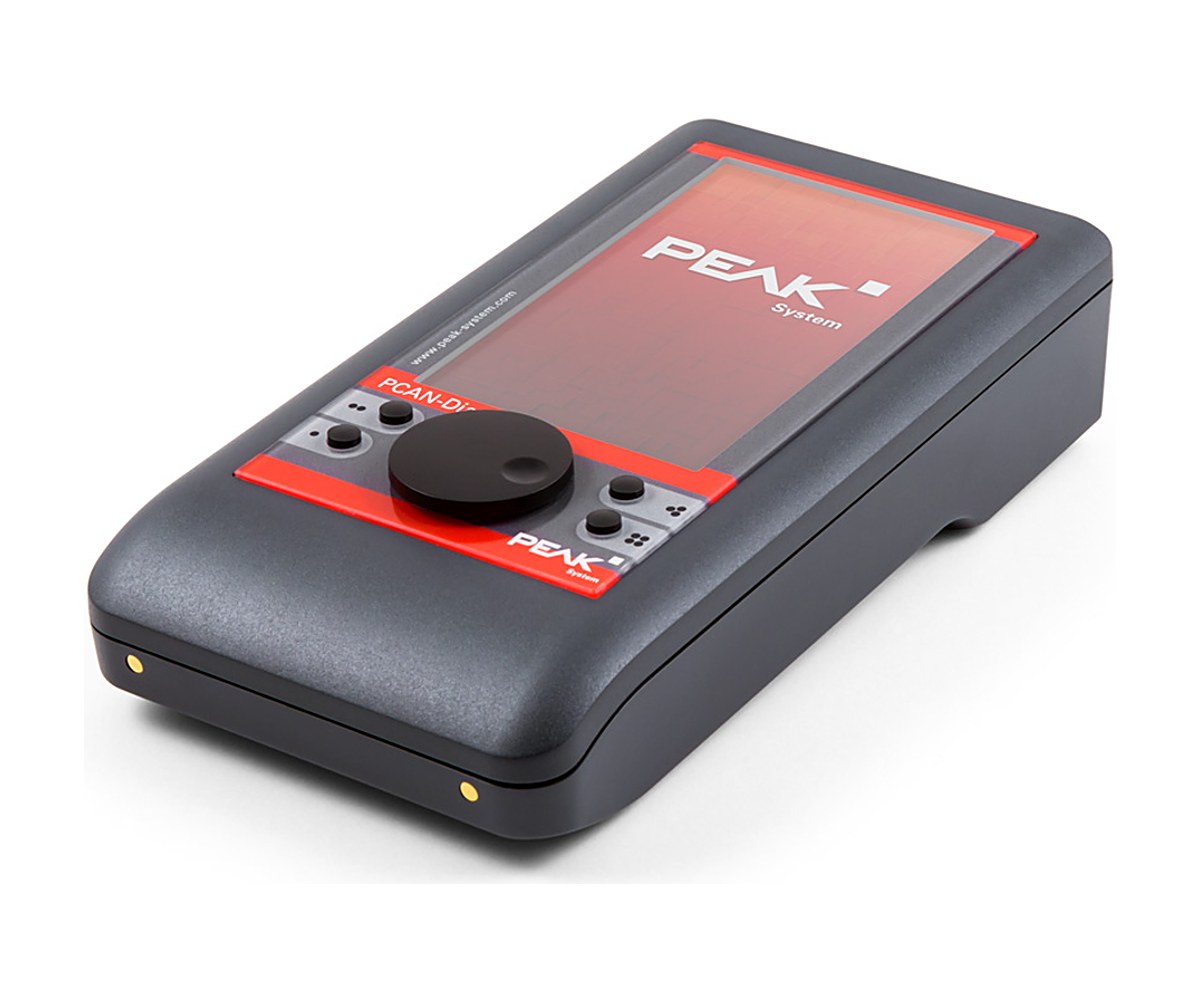
PCAN-Diag FD

PCAN-Diag FD

Handheld CAN and CAN FD tester with a 100 MHz two-channel scope

PCAN-Diag FD checks a CAN or CAN FD bus on two levels. On the protocol side it lists incoming frames, optionally with symbolic names, records traces, plays them back and transmits single frames or full sequences, for example to request diagnostic data.

On the physical side, a two-channel oscilloscope samples CAN-High and CAN-Low at up to 100 MHz each and decodes CAN and CAN FD frames from the waveform. It also measures bus load, termination and connector voltages. The internal batteries charge whenever external power is connected.

Highlights

  • CAN 2.0 and CAN FD at protocol and physical level
  • Two-channel scope, 100 MHz per channel, up to 1 megasample
  • Trigger on frame start or end, errors, CAN ID or the FD bit rate switch
  • Trace recording, playback and transmit sequences
  • 800 x 480 display plus micro HDMI output
  • Rechargeable batteries; optional quick-charging station

Software

  • PCAN-Diag FD Editor for Windows 11 (x64/ARM64) and 10 (x86/x64): settings, transmit lists, sequences and projects
  • PCAN-Symbol Editor: builds the Symbol files for symbolic display and transmission
  • PEAK-Converter: converts trace files to other formats

Options

  • IPEH-003068: charging station with quick-charge function
  • IPES-004069: J1939 Add-in licence

Key Specifications

SpecValue
Order numberIPEH-003069
CANHigh-speed CAN (ISO 11898-2), CAN 2.0 A/B and CAN FD, ISO and Non-ISO
Bit ratesCAN 20 kbit/s to 1 Mbit/s; CAN FD data 20 kbit/s to 12 Mbit/s
TransceiverMicrochip MCP2558FD
Oscilloscope2 channels, 100 MHz each, up to 1 megasample, time resolution up to 10 ns
Display800 x 480 pixels; micro HDMI out (DVI, 800 x 600)
PowerInternal rechargeable batteries or supplied power unit
Operating temperature0 to 50 C

In the Box

  • PCAN-Diag FD in a shockproof plastic case
  • PCAN-Diag FD Editor, PCAN-Symbol Editor and PEAK-Converter for Windows
  • USB cable
  • Power supply unit with Euro, US and UK plugs
  • Micro HDMI to DVI cable
  • Manual (PDF) and printed quick start guide

For quick checks with a smaller tool, see the PCAN-MiniDiag FD.

For quantities, lead time or a quote, contact Pertech.

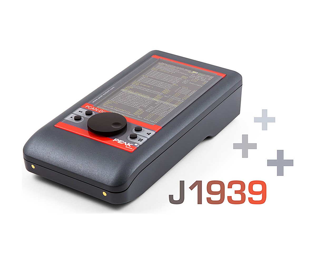
PCAN-Diag FD J1939 Add-in

PCAN-Diag FD J1939 Add-in

Read J1939 traffic on the PCAN-Diag FD in plain terms

This add-in teaches the PCAN-Diag FD handheld to speak SAE J1939, the CAN protocol used in trucks, buses and other utility vehicles. Traffic on the bus is decoded against the built-in J1939 database and shown as parameter groups and parameters instead of raw bytes.

It also reassembles multi-packet messages, follows address claiming and shows diagnostic messages and trouble codes. The add-in is a licence file bound to one device, so you can add it to a PCAN-Diag FD you already own.

Highlights

  • SAE J1939 decoding by PG and SP definitions
  • Full J1939 database included
  • Up to 20 custom PGs
  • Multi-packet messages up to 1,785 bytes
  • Address claiming support
  • DM and DTC diagnostic data display

Ordering

  • IPES-004069: licence for the J1939 Add-in, with database updates for 2 years
  • IPES-004069-Ext: extends the database updates by another 2 years
  • For a unit you already own, give us its serial number with the order. It is on the sticker under the device or in its support menu.

Key Specifications

SpecValue
Order numberIPES-004069
Runs onPCAN-Diag FD
ProtocolSAE J1939
Custom PGsUp to 20
Multi-packet payloadUp to 1,785 bytes
LicenceDevice-bound licence file
Database updates2 years from purchase, extendable

In the Box

  • Licence file to activate the J1939 Add-in
  • J1939 database updates for 2 years
  • Manual (PDF)

The add-in needs a PCAN-Diag FD. For J1939 on the PC, see the PCAN-Explorer 7 J1939 Add-in.

For quantities, lead time or a quote, contact Pertech.

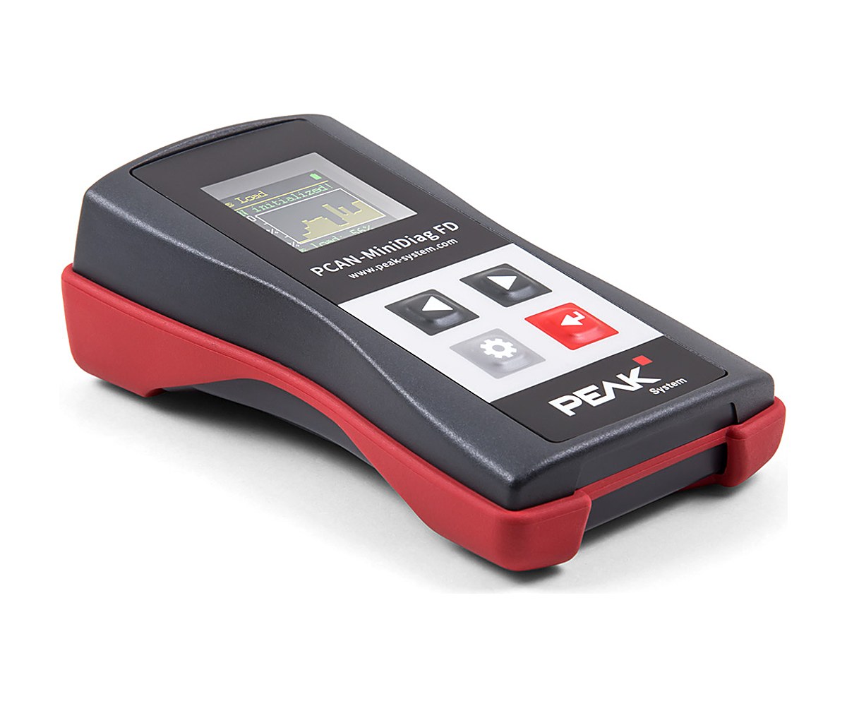
PCAN-MiniDiag FD

PCAN-MiniDiag FD

Pocket checker for CAN and CAN FD buses of unknown setup

PCAN-MiniDiag FD is a small handheld for first checks on a CAN or CAN FD bus. It measures the bit timing to find the nominal bit rate and, for CAN FD, the data bit rate, so you can connect to a vehicle or machine without knowing its configuration.

It also measures termination, bus load and the voltage levels on the CAN lines and connector, and counts CAN, CAN FD and error frames. It stays in listen-only mode all the time, so it never disturbs the bus. Three replaceable AAA batteries power it.

Highlights

  • Automatic CAN and CAN FD bit rate detection
  • Termination, bus load and voltage level measurement
  • Frame counters for CAN, CAN FD and errors
  • Permanent listen-only: no effect on the bus
  • IP42 casing with membrane keypad
  • Runs on AAA batteries

Functions

  • System Info: firmware and hardware version, serial number, battery voltage
  • D-Sub Voltages: pins 6 and 9, -40 to 43 V
  • CAN Min/Max and CAN Voltages: CAN-High and CAN-Low levels, -5 to 8 V
  • Termination, Bit Rate, Bus Load and Statistics

Key Specifications

SpecValue
Order numberIPEH-003070
CANHigh-speed CAN (ISO 11898-2), CAN 2.0 A/B and CAN FD, ISO and Non-ISO
Bit ratesCAN 10 kbit/s to 1 Mbit/s; CAN FD data 66.6 kbit/s to 10 Mbit/s
TransceiverMicrochip MCP2558FD
DisplayOLED, 128 x 128 pixels
Power3 x AAA batteries (1.2 V or 1.5 V)
ProtectionIP42
Size122 x 69 x 44 mm
Operating temperature-10 to 50 C

In the Box

  • PCAN-MiniDiag FD in plastic casing
  • AAA batteries
  • Manual (PDF) and printed quick start guide

For scope, trace and transmit functions, step up to the PCAN-Diag FD.

For quantities, lead time or a quote, contact Pertech.

PCAN-MiniDisplay

PCAN-MiniDisplay

Show CAN data on a small TFT screen, or log it to a card

PCAN-MiniDisplay is a small operator display for CAN systems. You describe the screen in text files: labels, numbers, images, image lists that change with a signal, and plotters. The unit then shows live data from its two High-speed CAN channels and its analog and digital inputs.

Alternatively it works as a data logger, recording traffic to a microSD card for replay or analysis on a PC. It runs one function at a time: a display configuration, recording or playback. A version in a plastic casing with three push buttons lets you switch between configurations while running.

Highlights

  • Two High-speed CAN channels, 40 kbit/s to 1 Mbit/s
  • 320 x 240 TFT display configured by text files
  • Numbers, text, bitmaps, image lists and plotters
  • CAN recording and playback on microSD (up to 32 GB)
  • 2 analog inputs, 1 digital input, 1 digital output
  • 7 to 30 V supply, -20 to 70 C

Versions

  • IPEH-002262: PCAN-MiniDisplay for building in, with mounting frame and cables
  • IPEH-002262-KSM01: PCAN-MiniDisplay in plastic casing with 3 push buttons and Phoenix mating connectors

Key Specifications

SpecValue
Order numberIPEH-002262 (built-in), IPEH-002262-KSM01 (casing)
CAN2 x High-speed CAN (ISO 11898-2), CAN 2.0 A/B, 40 kbit/s to 1 Mbit/s
TransceiverNXP TJA1041 with wake-up
DisplayTFT, 320 x 240 pixels
Analog inputs2, 10-bit, 0 to 16.5 V
MemorymicroSD slot (max. 32 GB), USB 2.0 access from a PC
Size80 x 55 mm
Supply7 to 30 V
Operating temperature-20 to 70 C

In the Box

  • PCAN-MiniDisplay (with mounting frame and cables, or in plastic casing with mating connectors)
  • 512 MB memory card fitted
  • PEAK-Converter for Windows
  • Configuration examples
  • Manual (PDF)

PEAK lists this product as end of life and says only smaller quantities remain. Check with us before you plan larger volumes.

For quantities, lead time or a quote, contact Pertech.

PCAN-Explorer 7

PCAN-Explorer 7

Monitor, decode, record and simulate CAN CC, CAN FD and CAN XL traffic from one Windows tool

PCAN-Explorer 7 is the PEAK-System workbench for engineers who work on CAN networks every day. It connects to up to 64 buses at once, shows the traffic in receive and transmit lists, and lets you send messages by hand or on a cycle to drive the bus for control tasks and simulations. Symbol files, or third-party databases through an add-in, turn raw IDs and hex bytes into named messages and signals.

Traces can be recorded from several buses at the same time and played back later, step by step or with breakpoints. For repetitive work, macros, Python, VBScript and native 64-bit callback libraries reach almost every part of the program. Version 7 adds CAN XL, a 64-bit core and a new licence model based on Wibu CodeMeter.

Highlights

  • CAN CC, CAN FD and CAN XL (ISO 11898-1:2024), up to 64 buses at once
  • Symbolic view of messages and signals from PEAK Symbol files or .dbc/.arxml databases
  • Multiple tracers and playbacks in parallel, with filters, breakpoints and single-step
  • Automation with macros, Python, VBScript and 64-bit callback DLLs
  • UDS Transmitter and UDS Downloader add-ins (beta) for diagnostics over ISO-TP
  • Single user or floating licence, on the PC or on a USB dongle, 12 months maintenance included

Editions and order numbers

  • IPES-007000: Single User Licence
  • IPES-007100: Single User Licence, Full Bundle
  • IPES-007200: Floating Licence
  • IPES-007300: Floating Licence, Full Bundle
  • The Full Bundle adds all four PCAN-Explorer 7 add-ins: Plotter, Instruments Panel, Bus Descriptions and J1939
  • Optional Wibu licence dongle: IPES-007090 (USB-A) or IPES-007091 (USB-C)

Licensing

  • Single user: tied to one computer, unlimited offline use once activated
  • Floating: a licence server on your own computer shares licences across the network, VPN included, with borrowing for offline use of up to 30 days
  • Both types can be bound to the computer or to a portable Wibu USB dongle and are managed with the PEAK License Manager
  • Licences are perpetual; the first 12 months of maintenance (updates, fixes and new major versions) are included and can be renewed
  • PEAK offers a free 30-day trial floating licence that includes all add-ins

Bus connection

  • Nominal bit rates up to 1 Mbit/s, CAN FD data rates up to 8 Mbit/s
  • CAN XL data rates up to 8 Mbit/s in CAN FD compatible mode, up to 20 Mbit/s with the transceiver mode switch
  • CAN XL with or without error signalling; CAN XL send messages with SDT selection to CiA 611-1, such as tunnelled CAN FD frames
  • Custom bit rates with automatic register calculation, listen-only per connection, hardware reset of the interface
  • Several CAN interfaces of different types can be used at the same time

Analysis and recording

  • Receive time stamps to 1 µs, transmit timing to 1 ms
  • Recording to file or to RAM (linear, dynamic or circular buffer), saved as TRC or CSV
  • MDF4, ASC and BLF handled through the free PEAK-Converter
  • Filters by channel, ID range, code/mask, symbols, error types, J1939 fields and CAN XL fields, on live traces or saved files
  • Watch window for live signal values; bus load available as a signal per connection

Requirements

  • Windows 11 (x64/ARM64) or Windows 10 (x64)
  • A PEAK-System PC CAN interface, with CAN FD or CAN XL support where needed
  • For a portable licence: a USB port for the dongle (USB-A or USB-C)
  • Internet connection recommended for activation

Key Specifications

SpecValue
Order numberIPES-007000 (single user); see editions for floating and Full Bundle
BusesCAN CC, CAN FD, CAN XL; up to 64 connections
Operating systemWindows 11 (x64/ARM64), Windows 10 (x64)
HardwarePEAK-System PC CAN interface
AutomationMacros, Python (embedded), VBScript, 64-bit callback DLLs
User interfaceEnglish, German or French
LicencePerpetual single user or floating (Wibu CodeMeter), on PC or USB dongle
DeliveryDownload

In the Box

  • PCAN-Explorer 7 installation files, including Wibu CodeMeter
  • Licence as ordered (single user or floating, standard or Full Bundle)
  • 12 months software maintenance
  • PCAN-Symbol Editor for Windows
  • Documentation in HTML format

Add-ins: Plotter Add-in, Instruments Panel Add-in, Bus Descriptions Add-in, J1939 Add-in. Users of the previous version can find PCAN-Explorer 6 here.

For a CAN XL connection, pair it with the PCAN-USB XL.

For quantities, lead time or a quote, contact Pertech.

PCAN-Explorer 7: Plotter Add-in

PCAN-Explorer 7: Plotter Add-in

Record and plot CAN signal curves live in PCAN-Explorer 7

The Plotter Add-in draws signals as curves over time while PCAN-Explorer 7 is connected. Signals can come from received or transmitted CAN messages, virtual variables or macro calculations, with no fixed limit on channels or Y-axes.

You can zoom and scroll the axes during a recording and measure with a cursor. Recordings export to CSV, the current view saves as an image, and CAN trace files (.trc) can be imported for plotting. The free PEAK Plot Viewer opens recordings on PCs without PCAN-Explorer.

Highlights

  • Real-time curves of CAN signals, virtual variables and macro results
  • Unlimited recording channels and Y-axes
  • Zoom and scroll during recording, measurement cursor
  • Logarithmic and reversible axes, limit values and ranges shown
  • CSV export, image export, import of .trc trace files

Order numbers

  • IPES-007087: Single user licence
  • IPES-007287: Floating licence

Requirements

  • PCAN-Explorer 7 with a matching licence
  • Windows 11 (x64/ARM64) or Windows 10 (x64), as for PCAN-Explorer 7

Key Specifications

SpecValue
Order numberIPES-007087 (single user), IPES-007287 (floating)
Base productPCAN-Explorer 7 with matching licence (required)
ChannelsUnlimited
Import and exportImports .trc; exports CSV and images
LicenceSingle user or floating
DeliveryDownload

In the Box

  • Licence (single user or floating)
  • Installation files for the Plotter Add-in

An add-in only runs inside PCAN-Explorer 7, so you need a PCAN-Explorer 7 licence of the matching type (single user or floating). It is also part of the PCAN-Explorer 7 Full Bundle. Other add-ins for PCAN-Explorer 7: Instruments Panel Add-in, Bus Descriptions Add-in, J1939 Add-in.

For quantities, lead time or a quote, contact Pertech.

PCAN-Explorer 7: Instruments Panel Add-in

PCAN-Explorer 7: Instruments Panel Add-in

Turn PCAN-Explorer 7 into a custom CAN dashboard, test panel or simulator

This add-in adds a panel editor to PCAN-Explorer 7 where you place gauges, indicators and controls. Signals from received CAN messages drive the displays, and switches, sliders, potentiometers and input fields send messages onto the bus.

Use it for simple simulations, test bench front panels or monitoring screens. Version 7 adds SVG image lists for drawing your own instruments, and panels can switch between layouts (scenes) depending on signal values.

Highlights

  • Analog and digital instruments fed by CAN signals
  • Controls and input fields that generate CAN messages
  • Own graphical instruments from image lists, including SVG since version 7
  • Scenes: different panel layouts selected by signal value at runtime
  • Automation through the panel object model with COM and scripts

Order numbers

  • IPES-007088: Single user licence
  • IPES-007288: Floating licence

Panel editing

  • Drag and drop or numeric positioning
  • Configure several elements at once in the property window
  • Shape elements: squares, rectangles, circles and ellipses
  • Save and load complete panel configurations

Requirements

  • PCAN-Explorer 7 with a matching licence
  • Windows 11 (x64/ARM64) or Windows 10 (x64), as for PCAN-Explorer 7

Key Specifications

SpecValue
Order numberIPES-007088 (single user), IPES-007288 (floating)
Base productPCAN-Explorer 7 with matching licence (required)
FunctionSignal display and CAN message generation
LicenceSingle user or floating
DeliveryDownload

In the Box

  • Licence (single user or floating)
  • Installation files for the Instruments Panel Add-in
  • Documentation in HTML help format

An add-in only runs inside PCAN-Explorer 7, so you need a PCAN-Explorer 7 licence of the matching type (single user or floating). It is also part of the PCAN-Explorer 7 Full Bundle. Other add-ins for PCAN-Explorer 7: Plotter Add-in, Bus Descriptions Add-in, J1939 Add-in.

For quantities, lead time or a quote, contact Pertech.

PCAN-Explorer 7: Bus Descriptions Add-in

PCAN-Explorer 7: Bus Descriptions Add-in

Work with CANdb and AUTOSAR XML databases directly in PCAN-Explorer 7

If your CAN messages are already defined in CANdb (.dbc) or AUTOSAR XML (.arxml) files, this add-in lets PCAN-Explorer 7 use them as they are. It combines the earlier CANdb import with new AUTOSAR XML support.

You choose which messages of a database to use and keep the selection in the project. With the PCAN-Symbol Editor you can also convert bus descriptions into the PEAK Symbol format, and export a Symbol file back to CANdb or AUTOSAR XML.

Highlights

  • Direct use of .dbc and .arxml files in PCAN-Explorer 7
  • Pick the messages you need from a database
  • Selection saved in the PCAN-Explorer project
  • Import into the PEAK Symbol format
  • Export from a Symbol file to CANdb or AUTOSAR XML

Order numbers

  • IPES-007086: Single user licence
  • IPES-007286: Floating licence

Requirements

  • PCAN-Explorer 7 with a matching licence
  • Windows 11 (x64/ARM64) or Windows 10 (x64), as for PCAN-Explorer 7

Key Specifications

SpecValue
Order numberIPES-007086 (single user), IPES-007286 (floating)
Base productPCAN-Explorer 7 with matching licence (required)
File formatsCANdb (.dbc), AUTOSAR XML (.arxml)
LicenceSingle user or floating
DeliveryDownload

In the Box

  • Licence (single user or floating)
  • Installation files for the Bus Descriptions Add-in
  • Documentation in HTML help format

An add-in only runs inside PCAN-Explorer 7, so you need a PCAN-Explorer 7 licence of the matching type (single user or floating). It is also part of the PCAN-Explorer 7 Full Bundle. Other add-ins for PCAN-Explorer 7: Plotter Add-in, Instruments Panel Add-in, J1939 Add-in.

For quantities, lead time or a quote, contact Pertech.

PCAN-Explorer 7: J1939 Add-in

PCAN-Explorer 7: J1939 Add-in

J1939 and J1939 FD decoding, transmission and diagnostics in PCAN-Explorer 7

SAE J1939 is the CAN protocol of utility vehicles for control and diagnostic data, built on 29-bit identifiers. This add-in brings J1939 to PCAN-Explorer 7, both the classic J1939-21 over CAN CC and J1939 FD (J1939-22) over CAN FD, and shows the data interpreted by parameter group and SP definitions.

A J1939 database with the definitions and parameters is included and receives regular updates while a maintenance contract is active. You can also define your own parameter groups, starting from entries in the database. PEAK allows the database to be used only with PCAN-Explorer 7 and this add-in.

Highlights

  • SAE J1939-21 (CAN CC) and J1939-22 (CAN FD, J1939 FD)
  • J1939 database included, updated with active maintenance
  • Custom parameter groups, also based on database entries
  • Broadcast or ECU-specific messages, address claiming and multi-packet messages
  • Monitor window to show and request Diagnostic Trouble Codes (DTCs)

Order numbers

  • IPES-007089: Single user licence
  • IPES-007289: Floating licence

Requirements

  • PCAN-Explorer 7 with a matching licence
  • Windows 11 (x64/ARM64) or Windows 10 (x64), as for PCAN-Explorer 7

Key Specifications

SpecValue
Order numberIPES-007089 (single user), IPES-007289 (floating)
Base productPCAN-Explorer 7 with matching licence (required)
ProtocolSAE J1939-21 and J1939-22 (J1939 FD)
LicenceSingle user or floating
DeliveryDownload

In the Box

  • Licence (single user or floating)
  • Installation files for the J1939 Add-in
  • J1939 database
  • Documentation in HTML help format

An add-in only runs inside PCAN-Explorer 7, so you need a PCAN-Explorer 7 licence of the matching type (single user or floating). It is also part of the PCAN-Explorer 7 Full Bundle. Other add-ins for PCAN-Explorer 7: Plotter Add-in, Instruments Panel Add-in, Bus Descriptions Add-in.

To connect to a vehicle, see the PCAN-Cable J1939.

For quantities, lead time or a quote, contact Pertech.

PCAN-Explorer 6

PCAN-Explorer 6

CAN and CAN FD analysis for Windows, now in its end-of-life phase

PCAN-Explorer 6 is PEAK-System’s earlier Windows tool for watching and driving CAN and CAN FD networks. It shows bus traffic in receive and transmit lists, sends messages by hand, cyclically or from transmit lists, and handles several buses at once with any mix of PEAK interfaces. Symbol files translate IDs and raw bytes into named signals, and traces can be recorded and played back.

PEAK has put version 6 into end of life. The single computer licence and the add-ins remain on sale until 28 January 2027, the portable dongle licence has already been withdrawn, and maintenance and support stop on 28 January 2028. For new installations PEAK recommends PCAN-Explorer 7.

Highlights

  • CAN 2.0 A/B and CAN FD, up to 16 channels
  • Data bit rates up to 12 Mbit/s with a CAN FD interface
  • Symbolic message and signal view from PEAK Symbol files
  • Multiple tracers, recording to file or RAM, trace playback
  • Automation with macros, VBScript and 32-bit callback DLLs
  • Add-ins for plotting, instrument panels, CANdb import and J1939

Versions

  • IPES-006000: PCAN-Explorer 6 Single Computer Licence (orderable until 28 January 2027)
  • Portable Licence with USB dongle (IPES-006000 + IPES-006090): already discontinued
  • Add-ins: Plotter Add-in 6, Instruments Panel Add-in 6, CANdb Import Add-in 6, J1939 Add-in 6 (orderable until 28 January 2027)

Requirements

  • Windows 11 (x64/ARM64) or Windows 10 (x86/x64)
  • A free USB port for the installation stick
  • A PEAK-System CAN interface for the bus connection
  • Internet connection recommended for activation

Key Specifications

SpecValue
Order numberIPES-006000 (single computer licence)
StatusEnd of life; sales until 28 January 2027, support until 28 January 2028
BusesCAN 2.0 A/B and CAN FD, up to 16 channels
Bit ratesNominal up to 1 Mbit/s; CAN FD data up to 12 Mbit/s
Time resolutionReceive 1 µs, transmit 1 ms
AutomationMacros, VBScript, 32-bit callback DLLs
User interfaceEnglish or German
Operating systemWindows 11 (x64/ARM64), Windows 10 (x86/x64)

In the Box

  • PCAN-Explorer 6 licence and installation files on USB stick
  • PCAN-Symbol Editor for Windows
  • Documentation in HTML format

Add-ins: Plotter Add-in 6 and J1939 Add-in 6. For new projects, see PCAN-Explorer 7.

For PCAN-Explorer 7, add-ins or a quote, contact Pertech.

PCAN-Explorer 6: Plotter Add-in 6

PCAN-Explorer 6: Plotter Add-in 6

Plot CAN signals over time in PCAN-Explorer 6

The Plotter Add-in records signals and draws them as curves while the bus is running. Sources can be signals from received or transmitted CAN messages, virtual variables, or values calculated by macros, and there is no fixed limit on channels or Y-axes.

Axes can be zoomed and scrolled during a recording, and a cursor helps you measure on the plot. Recordings export to CSV, views save as images, and recordings from the PCAN-Explorer tracer, PCAN-Trace or PCAN-View can be loaded for plotting. PEAK also offers the free Plot Viewer to open plots on PCs without PCAN-Explorer.

Highlights

  • Live curves of CAN signals, virtual variables and macro results
  • Unlimited recording channels and Y-axes
  • Zoom and scroll while recording, measurement cursor
  • Logarithmic and reversible axes, limit values and ranges shown
  • Export to CSV; save views as EMF, PNG, BMP or JPEG

Data import

  • Recordings from the PCAN-Explorer tracer, PCAN-Trace and PCAN-View

Requirements

  • PCAN-Explorer 6 (licensed)
  • Windows 11 (x64/ARM64) or Windows 10 (x86/x64)
  • A free USB port for the installation stick and the copy protection dongle

Key Specifications

SpecValue
Order numberIPES-006087
Base productPCAN-Explorer 6 (required)
ChannelsUnlimited
ExportCSV data; EMF, PNG, BMP, JPEG images
Operating systemWindows 11 (x64/ARM64), Windows 10 (x86/x64)
LicenceSingle computer licence or portable licence with USB copy protection dongle
DeliveryUSB stick

In the Box

  • Licence (single computer or USB dongle)
  • Installation files for the Plotter Add-in

This add-in extends PCAN-Explorer 6 and needs a licensed PCAN-Explorer 6 installation. Other add-ins for PCAN-Explorer 6: Instruments Panel Add-in 6, CANdb Import Add-in 6, J1939 Add-in 6.

For PCAN-Explorer 7, order the PCAN-Explorer 7 Plotter Add-in.

For quantities, lead time or a quote, contact Pertech.

PCAN-Explorer 6: Instruments Panel Add-in 6

PCAN-Explorer 6: Instruments Panel Add-in 6

Build your own CAN dashboard and control panel in PCAN-Explorer 6

The Instruments Panel Add-in gives PCAN-Explorer 6 a drag-and-drop panel of gauges, indicators and controls. Signals decoded from incoming CAN messages drive the displays, while switches, sliders, potentiometers and input fields put messages on the bus.

That makes it practical for quick simulations of CAN applications and for operator screens on a test bench. Panels can hold several scenes that change at runtime, and the whole panel can be automated through its object model with COM and scripts.

Highlights

  • Analog and digital instruments driven by CAN signals
  • Switches, sliders, potentiometers and input fields that transmit CAN messages
  • Analog 360° gauge and shape elements (squares, rectangles, circles, ellipses)
  • Several scenes on one panel, switched at runtime or by signal value
  • Automation through COM and scripts

Panel editing

  • Free placement by drag and drop or by numeric position
  • Select and configure several elements at once in the property window
  • Signal-dependent image lists and scenes
  • Save and load complete panel configurations

Requirements

  • PCAN-Explorer 6 (licensed)
  • Windows 11 (x64/ARM64) or Windows 10 (x86/x64)
  • A free USB port for the installation stick and the copy protection dongle

Key Specifications

SpecValue
Order numberIPES-006088
Base productPCAN-Explorer 6 (required)
FunctionSignal display and CAN message generation
Operating systemWindows 11 (x64/ARM64), Windows 10 (x86/x64)
LicenceSingle computer licence or portable licence with USB copy protection dongle
DeliveryUSB stick

In the Box

  • Licence (single computer or USB dongle)
  • Installation files for the Instruments Panel Add-in
  • Documentation in HTML help format

This add-in extends PCAN-Explorer 6 and needs a licensed PCAN-Explorer 6 installation. Other add-ins for PCAN-Explorer 6: Plotter Add-in 6, CANdb Import Add-in 6, J1939 Add-in 6.

For PCAN-Explorer 7, order the PCAN-Explorer 7 Instruments Panel Add-in.

For quantities, lead time or a quote, contact Pertech.

PCAN-Explorer 6: CANdb Import Add-in 6

PCAN-Explorer 6: CANdb Import Add-in 6

Use your existing CANdb files in PCAN-Explorer 6 instead of retyping them

Many vehicle and machine projects already describe their CAN messages in CANdb (.dbc) files. This add-in lets PCAN-Explorer 6 open those files directly, so you do not have to copy the definitions by hand into the PCAN-Explorer symbol format.

You pick which messages from the database you want to use, and the selection is kept in the PCAN-Explorer project. The data can also be saved as a PCAN-Explorer symbol file.

Highlights

  • Opens CANdb (.dbc) files in PCAN-Explorer 6
  • Choose which messages of the database to use
  • Selection stored with the PCAN-Explorer project
  • Saves to the PCAN-Explorer symbol format

Requirements

  • PCAN-Explorer 6 (licensed)
  • Windows 11 (x64/ARM64) or Windows 10 (x86/x64)
  • A free USB port for the installation stick and the copy protection dongle

Key Specifications

SpecValue
Order numberIPES-006086
Base productPCAN-Explorer 6 (required)
File formatCANdb (.dbc)
Operating systemWindows 11 (x64/ARM64), Windows 10 (x86/x64)
LicenceSingle computer licence or portable licence with USB copy protection dongle
DeliveryUSB stick

In the Box

  • Licence (single computer or USB dongle)
  • Installation files for the CANdb Import Add-in
  • Documentation in HTML help format

This add-in extends PCAN-Explorer 6 and needs a licensed PCAN-Explorer 6 installation. Other add-ins for PCAN-Explorer 6: Plotter Add-in 6, Instruments Panel Add-in 6, J1939 Add-in 6.

In PCAN-Explorer 7, the same job is done by the Bus Descriptions Add-in, which also reads AUTOSAR XML.

For quantities, lead time or a quote, contact Pertech.

PCAN-Explorer 6: J1939 Add-in 6

PCAN-Explorer 6: J1939 Add-in 6

Read and send SAE J1939 parameters by name in PCAN-Explorer 6

SAE J1939 is the CAN protocol used in trucks, buses, agricultural and other utility vehicles for control and diagnostic data, built on 29-bit extended identifiers. This add-in teaches PCAN-Explorer 6 the parameter groups defined by the standard, so you work with named parameters instead of raw IDs and bytes.

It comes with a J1939 database (revision September 2024) that holds the definitions and parameters. PEAK allows that database to be used only together with PCAN-Explorer and this add-in. J1939 FD (SAE J1939-22 over CAN FD) is not supported in this version.

Highlights

  • SAE J1939 parameter groups decoded by name
  • J1939 database included (revision September 2024)
  • Broadcast messages or messages to individual ECUs, up to 254 addresses
  • Multi-packet messages supported
  • Monitor window to show and request Diagnostic Trouble Codes (DTCs)

Requirements

  • PCAN-Explorer 6 (licensed)
  • Windows 11 (x64/ARM64) or Windows 10 (x86/x64)
  • A free USB port for the installation stick and the copy protection dongle

Key Specifications

SpecValue
Order numberIPES-006089
Base productPCAN-Explorer 6 (required)
ProtocolSAE J1939 on CAN (J1939-22 for CAN FD not supported)
ECU addressingUp to 254 ECUs
Operating systemWindows 11 (x64/ARM64), Windows 10 (x86/x64)
LicenceSingle computer licence or portable licence with USB copy protection dongle
DeliveryUSB stick

In the Box

  • Licence (single computer or USB dongle)
  • Installation files for the J1939 Add-in
  • J1939 database
  • Documentation in HTML help format

This add-in extends PCAN-Explorer 6 and needs a licensed PCAN-Explorer 6 installation. Other add-ins for PCAN-Explorer 6: Plotter Add-in 6, Instruments Panel Add-in 6, CANdb Import Add-in 6.

For J1939 FD support, see the PCAN-Explorer 7 J1939 Add-in; for a vehicle connection, the PCAN-Cable J1939.

For quantities, lead time or a quote, contact Pertech.

PCAN-Developer 5

PCAN-Developer 5

Professional CAN API for Windows applications, with CAN XL and CAN FD light support

PCAN-Developer 5 is the professional PEAK programming package for Windows applications that talk to CAN CC, CAN FD, CAN FD light and CAN XL. Its PCAN-API comes as interface DLLs for x86, x64 and ARM64.

Unlike PCAN-Basic, communication runs through Clients connected to Nets. Up to 127 applications can share one physical CAN channel, and Clients can also talk to each other over virtual Nets with no hardware attached, which helps when you test software before the bus is available.

Highlights

  • CAN CC, CAN FD (ISO and non-ISO), CAN FD light and CAN XL (ISO 11898-1:2024)
  • Up to 127 applications per physical CAN channel, up to 127 channels per hardware type
  • Virtual Nets for simulated CAN traffic between applications
  • Up to 32,768 buffered messages per Client, time stamps to 1 µs (interface dependent)
  • C/C++, Pascal OO and Python headers; .NET assembly for C#, VB.NET and C++/CLR
  • Redistribution licence for the PCAN-Developer runtime included

Clients and Nets

  • A Net joins one CAN connection (or none) with any number of Clients
  • A Client can connect to several Nets
  • A message sent by one Client reaches all other Clients on the Net and the external bus
  • Access to the CAN channels of a PCAN-Gateway through the PCAN-LAN hardware type

API features

  • Windows events on message reception and driver events for parameter changes, plug-in and plug-out, and bus load
  • Transmit timing set by time stamps; single-shot and self-receive transmissions
  • Error frame reception and generation
  • Configurable buffer size and a free message filter per Client
  • Listen-only and other hardware parameters, hardware reset during a connection
  • Thread-safe API

Licence

  • Single user licence for the development package
  • Distribution licence for the PCAN-Developer redistributable (API DLLs, PCAN-View, PCAN-Nets Configuration, PCAN-Status Display, API-Guide)
  • One year of updates and free support for the API and the software

Requirements

  • Develops applications for Windows 11 (x64/ARM64) and Windows 10 (x86/x64); the package itself runs on Windows 11 (x64/ARM64) or Windows 10 (x64)
  • PEAK-System PC CAN interface for the bus connection

Key Specifications

SpecValue
Order numberNot listed on the PEAK page; contact Pertech
BusesCAN CC, CAN FD, CAN FD light, CAN XL
PlatformsWindows 11 (x64/ARM64), Windows 10 (x86/x64)
LanguagesC/C++, Pascal OO, Python, C#, VB.NET, C++/CLR
Applications per channelUp to 127
LicenceSingle user development licence plus redistribution licence
DeliveryDownload

In the Box

  • PCAN-API interface DLLs (x86/x64/ARM64)
  • PCAN-Developer licence package
  • PCAN-View, PCAN-Nets Configuration, PCAN-Status Display and PCAN-Developer API-Guide
  • Header files for C/C++, Pascal OO and Python; assembly for C#, VB.NET and C++/CLR
  • Examples for all supported languages
  • Documentation in PDF format

For CAN XL hardware, see the PCAN-USB XL; other suitable interfaces include the PCAN-USB FD and PCAN-USB Pro FD.

For quantities, lead time or a quote, contact Pertech.

CANopen Magic

CANopen Magic

Configure, monitor, analyse and simulate CANopen and CANopen FD networks

CANopen Magic from Embedded Systems Academy is a Windows tool for CANopen and CANopen FD devices and networks. It reads and writes objects over SDO, interprets the trace symbolically (which node, which object) and records long traces, all through a PEAK-System PC CAN interface.

It comes in three editions. Lite covers SDO access and symbolic tracing; Professional adds PDO configuration, graphs, EDS import, LSS and command line control; Ultimate adds simulation of CANopen devices from EDS files and network and trace analysis diagrams.

Highlights

  • CANopen and CANopen FD
  • SDO read and write in expedited, segmented and block modes
  • Symbolic trace interpretation and long-term recording
  • Professional: PDO configuration, EDS import, CiA 447 support, LSS master, command line
  • Ultimate: device simulation from EDS files, network and trace analysis diagrams

Editions and order numbers

  • IPES-002098: CANopen Magic Lite
  • IPES-002084: CANopen Magic Professional
  • IPES-002097: CANopen Magic Ultimate

All editions

  • Read and write objects with SDO transfers (expedited, segmented, block)
  • Symbolic trace interpretation
  • Long-term trace recording
  • CANopen FD support

Professional adds

  • Simplified PDO configuration window
  • Graphical data display
  • Symbolic information imported from CANopen EDS files
  • Several symbolic trace windows, each with its own filters
  • Complex application profiles such as CiA 447
  • Integrated LSS master
  • Command line support

Ultimate adds

  • Simulation of CANopen devices based on EDS files
  • Network diagram
  • Trace analysis diagram

Requirements

  • Windows 11, 10, 8.1, 7, Vista or XP (32/64-bit)
  • At least 512 MB RAM and a 1 GHz CPU
  • Internet connection (for registration)
  • PEAK-System PC CAN interface

Key Specifications

SpecValue
Order numberIPES-002084 (Professional); Lite IPES-002098, Ultimate IPES-002097
DeveloperEmbedded Systems Academy (EmSA)
ProtocolsCANopen, CANopen FD
Operating systemWindows 11, 10, 8.1, 7, Vista, XP (32/64-bit)
HardwarePEAK-System PC CAN interface
LicenceSingle use, bound to one computer through online registration
DeliveryElectronic, to the e-mail address given with the order

In the Box

  • CANopen Magic licence in the ordered edition
  • Installation files (electronic delivery)

To build your own CANopen PC application, see the CANopen Magic Pro DLL or the CANopen Controller Library. For CANopen FD, use an interface such as the PCAN-USB FD.

Please give the e-mail address of the person who will install the software when you order.

For quantities, lead time or a quote, contact Pertech.

CANopen Magic Pro DLL – The CANopen PC Developer’s Kit

CANopen Magic Pro DLL – The CANopen PC Developer’s Kit

Build your own CANopen and CANopen FD PC applications on the CANopen Magic engine

CANopen Magic Pro DLL packages the CANopen functions of CANopen Magic as a DLL for your own software. It pairs a CANopen DLL with the PCAN-API from PCAN-Developer 3, which handles communication with the connected PEAK interface.

The kit is aimed at custom analysis and test programs, for example on production lines or for field service and maintenance, for both CANopen and CANopen FD. C header files, libraries and import files for common PC development environments are included.

Highlights

  • CANopen and CANopen FD functions of CANopen Magic as a DLL
  • Includes the PCAN-API from PCAN-Developer 3 for the interface connection
  • C header files, libraries and import files for common development environments
  • For custom test, production and service applications

Requirements

  • Windows 11, 10, 8.1, 7, Vista or XP (32/64-bit)
  • At least 512 MB RAM and a 1 GHz CPU
  • PEAK-System PC CAN interface

Key Specifications

SpecValue
Order numberIPES-002089
DeveloperEmbedded Systems Academy (EmSA)
ProtocolsCANopen, CANopen FD
Interface layerPCAN-API (PCAN-Developer 3)
Operating systemWindows 11, 10, 8.1, 7, Vista, XP (32/64-bit)
DeliveryElectronic, to the e-mail address given with the order

In the Box

  • CANopen DLL
  • PCAN-API from PCAN-Developer 3
  • C header files, libraries and import files
  • Documentation

For interactive work without programming, see CANopen Magic; for a self-configuring manager on PCAN-Basic, the CANopen Controller Library.

Please give the e-mail address of the developer who will receive the software when you order.

For quantities, lead time or a quote, contact Pertech.

CANopen Controller Library

CANopen Controller Library

Access a whole CANopen network from a Windows program with minimal CANopen knowledge

The CANopen Controller Library (CANopenIA-MGR) from Embedded Systems Academy (EmSA) is a compact CANopen manager and master that configures itself. At start-up it scans the network and sets itself up to send and receive the relevant communication, so your host program can reach every node straight away.

Your code addresses a parameter by node ID and Object Dictionary entry; the library decides whether to use a PDO or an SDO. It runs on top of the PEAK PCAN-Basic DLL, so it works on any Windows PC with the PCAN drivers installed.

Highlights

  • Self-configuring CANopen manager and master
  • Automatic network scan at start-up
  • Access any parameter by node ID and Object Dictionary entry
  • Chooses PDO or SDO automatically
  • Examples: command line demo, Java and C programming examples

Licensing

  • The commercial version needs a signed licence agreement
  • One runtime licence per PCAN device that uses the library: order one item per PCAN interface
  • A time- and feature-limited evaluation version is offered by PEAK as a free download

Requirements

  • Windows 11, 10, 8.1, 7, Vista or XP (32/64-bit)
  • At least 512 MB RAM and a 1 GHz CPU
  • PEAK-System PC CAN interface with PCAN drivers

Key Specifications

SpecValue
Order numberNot listed by PEAK; contact Pertech
DeveloperEmbedded Systems Academy (EmSA)
ProtocolCANopen manager and master
Interface layerPEAK PCAN-Basic DLL
Operating systemWindows 11, 10, 8.1, 7, Vista, XP (32/64-bit)
LicenceSigned licence agreement plus one runtime licence per PCAN interface
DeliveryElectronic

In the Box

  • CANopen Controller Library
  • Runtime licence (one per PCAN interface)
  • Command line demo and Java and C programming examples

For interactive CANopen work, see CANopen Magic; for a full CANopen DLL, the CANopen Magic Pro DLL. It runs with PEAK PC interfaces such as the PCAN-USB and PCAN-USB FD.

For quantities, lead time or a quote, contact Pertech.

PCI-PC/104-Plus Adapter

PCI-PC/104-Plus Adapter

Run a PC/104-Plus card in a desktop PCI slot

This adapter lets you plug a PC/104-Plus card into a PC with a PCI slot and operate it there, which is handy for testing a card on a desktop machine before it goes into an embedded stack.

It is a two-layer board with gold-plated PCI contacts. PEAK offers it only in limited quantities.

Highlights

  • Operates a PC/104-Plus card in a PCI slot
  • Two-layer board
  • Gold-plated PCI contacts

Key Specifications

SpecValue
Order numberIPEH-003028-XL
Host slotPCI
HoldsOne PC/104-Plus card
BoardTwo-layer, gold-plated PCI contacts

In the Box

  • PCI-PC/104-Plus Adapter

It can be used to test cards such as the PCAN-PC/104-Plus in a desktop PC.

For quantities, lead time or a quote, contact Pertech.

PCIe-miniPCIe Low-Profile Adapter

PCIe-miniPCIe Low-Profile Adapter

Run PCI Express Mini cards in a low-profile PC

The PCIe-miniPCIe Low-Profile Adapter lets a low-profile PC take PCI Express Mini and Half PCI Express Mini cards in a PCIe x1 slot. Two movable spacers hold the card in place.

Besides the PCAN-miniPCIe, the adapter suits USB solutions and wireless cards for WLAN, WWAN and WPAN. It has a Mini-USB socket, a Micro-SIM holder for UMTS and GSM cards, and supplies 1.5 V and 3.3 V to the plugged card.

Highlights

  • Low-profile PCIe x1 card
  • Fits full and half-size PCI Express Mini cards
  • Mini-USB socket and Micro-SIM holder
  • 1.5 V and 3.3 V for the plugged card
  • Operating range -40 to +85 C

Key Specifications

SpecValue
Order numberIPEH-003029
Form factorLow profile, PCIe x1, 4-layer board
Card holderPCI Express Mini and Half PCI Express Mini
ExtrasMini-USB socket, Micro-SIM holder, status LEDs
Card supply1.5 V and 3.3 V
Operating temperature-40 to +85 C

In the Box

  • PCIe-miniPCIe Low-Profile Adapter with mounted D-Sub slot bracket and connection cable
  • Manual in PDF format

It is made for cards such as the PCAN-miniPCIe and the PCAN-miniPCIe FD.

For quantities, lead time or a quote, contact Pertech.

PCIe-M.2 Low-Profile Adapter

PCIe-M.2 Low-Profile Adapter

Use a PCAN-M.2 card in a low-profile PCI Express PC

The PCIe-M.2 Low-Profile Adapter carries an M.2 plug-in card in a PCI Express x1 slot of a low-profile PC. It is designed mainly for the PCAN-M.2 CAN interface.

Up to four CAN channels can be connected through the regular D-Sub cables of the PCAN-M.2, a 10-pin pin connector or solder pads. Each channel has a split termination that you activate with a solder jumper.

Highlights

  • Low-profile PCIe x1 card
  • Screw mount for an M.2 2260 M-Key card
  • Up to four CAN channels via D-Sub cable, pin header or solder pads
  • Per-channel CAN termination by solder jumper
  • Operating range -40 to +85 C

Key Specifications

SpecValue
Order numberIPEH-003023
Form factorLow profile, PCIe x1
Card holderM.2 type 2260, M-Key
CAN connectionD-Sub cable of the PCAN-M.2, 10-pin pin connector, or solder pads
TerminationPer channel, via solder jumpers
Supply3.3 V
Operating temperature-40 to +85 C

In the Box

  • PCIe-M.2 Low-Profile Adapter with mounted slot bracket
  • Manual in PDF format

It is made for the PCAN-M.2.

For quantities, lead time or a quote, contact Pertech.

PCAN-Term

PCAN-Term

Plug-in 120-ohm termination for the ends of a CAN or CAN FD bus

Each end of a High-speed CAN bus (ISO 11898-2) needs a termination resistor. If no node sits at an end, or the node there has no termination of its own, PCAN-Term closes the bus with a 120-ohm resistor between CAN_L and CAN_H.

It has a D-Sub socket on one side and a D-Sub connector on the other, so it can sit inline at a device or at the end of a cable. It comes in two housings: PCAN-Term in a plastic case and the smaller PCAN-MiniTerm in a molded body. Both work on CAN FD buses.

Highlights

  • 120-ohm resistor between CAN_L and CAN_H
  • 9-pin D-Sub socket to 9-pin D-Sub connector (CiA 106)
  • Plastic case (PCAN-Term) or molded body (PCAN-MiniTerm)
  • Usable on CAN FD buses

Versions and order numbers

  • IPEK-003002: PCAN-Term, plastic case
  • IPEK-003002-Mini: PCAN-MiniTerm, molded body, all pins connected 1 to 1

Key Specifications

SpecValue
Order numbersIPEK-003002, IPEK-003002-Mini
Connectors9-pin D-Sub socket to 9-pin D-Sub connector (CiA 106)
Termination120 ohm between CAN_L and CAN_H
HousingPCAN-Term: plastic case. PCAN-MiniTerm: molded body
CAN FDSuitable

In the Box

  • PCAN-Term or PCAN-MiniTerm, in the version ordered

Use it with PCAN-Cable 1 and the PCAN-T-Adapter to put together a bus with tap points. For loose wire ends, see the PCAN-Adapter D-Sub to Screw Terminals.

For quantities, lead time or a quote, contact Pertech.

PCAN-T-Adapter

PCAN-T-Adapter

Add another node to a running CAN or CAN FD bus

PCAN-T-Adapter puts a branch into an existing CAN bus. It taps the data lines and ground and brings them out on a short tap cable with its own D-Sub socket, ready for one more CAN node.

The tap has no termination, so the bus keeps its termination at the two ends. There are two housings: PCAN-T-Adapter in a plastic case and PCAN-Mini-T-Adapter in a molded body. Both work on CAN FD buses.

Highlights

  • D-Sub socket in, D-Sub connector and D-Sub socket out (CiA 106)
  • Tap cable of about 20 cm
  • No termination
  • Plastic case or molded body
  • Usable on CAN FD buses

Versions and order numbers

  • IPEK-003003: PCAN-T-Adapter, plastic case
  • IPEK-003003-Mini: PCAN-Mini-T-Adapter, molded body

Key Specifications

SpecValue
Order numbersIPEK-003003, IPEK-003003-Mini
Connectors9-pin D-Sub socket to 9-pin D-Sub connector and 9-pin D-Sub socket (CiA 106)
Tap lengthAbout 20 cm (cable color on the PCAN-T-Adapter may vary)
TerminationNone
HousingPCAN-T-Adapter: plastic case. PCAN-Mini-T-Adapter: molded body
CAN FDSuitable

In the Box

  • PCAN-T-Adapter or PCAN-Mini-T-Adapter, in the version ordered

Combine it with PCAN-Cable 1 for the bus segments and the PCAN-Term at both ends.

For quantities, lead time or a quote, contact Pertech.

PCAN-Adapter D-Sub for DR Products

PCAN-Adapter D-Sub for DR Products

Standard D-Sub CAN cables for PEAK devices in DIN rail housings

PEAK devices in DIN rail housings bring CAN out on a 4-pin screw terminal block. This adapter maps those terminals to a 9-pin D-Sub connector, so the standard PEAK CAN cables connect the device to a PC CAN interface without loose wiring.

It has no termination and can be used on CAN FD buses.

Highlights

  • 4-pin Phoenix screw terminal to 9-pin D-Sub
  • D-Sub wired to CiA 106
  • Fits PEAK DR products
  • No termination
  • Usable on CAN FD buses

Key Specifications

SpecValue
Order numberIPEK-003012
Connectors4-pin screw terminal block (Phoenix) to 9-pin D-Sub (CiA 106)
ForPCAN-Repeater DR, PCAN-Router DR, PCAN-Ethernet Gateway DR, PCAN-Ethernet Gateway FD DR, PCAN-Wireless Gateway DR
TerminationNone

In the Box

  • PCAN-Adapter D-Sub for DR products

It fits the PCAN-Repeater DR, PCAN-Router DR, PCAN-Ethernet Gateway DR and PCAN-Ethernet Gateway FD DR. For the PCAN-Repeater, use the Ixxat CAN Adapter Screw Terminals to D-Sub 9.

For quantities, lead time or a quote, contact Pertech.

Ixxat CAN Adapter Screw Terminals to D-Sub 9

Ixxat CAN Adapter Screw Terminals to D-Sub 9

Give the PCAN-Repeater a standard D-Sub CAN connector

This Ixxat adapter turns the 4-pin CAN screw terminal of the PCAN-Repeater into a standard 9-pin D-Sub connector. You can then use ordinary PEAK CAN cables between the repeater and a PC CAN interface.

The adapter works on CAN and CAN FD buses. It is intended for the PCAN-Repeater only; other PEAK devices in DIN rail housings use the PCAN-Adapter D-Sub for DR Products.

Highlights

  • 4-pin Phoenix screw terminal to 9-pin D-Sub
  • D-Sub wired to CiA 106
  • No termination
  • Usable on CAN FD buses

Key Specifications

SpecValue
Order number1.04.0074.03000
Connectors4-pin screw terminal block (Phoenix) to 9-pin D-Sub (CiA 106)
ForPCAN-Repeater
TerminationNone

In the Box

  • Ixxat CAN adapter screw terminals to D-Sub 9

It is made for the PCAN-Repeater. For the PCAN-Repeater DR, PCAN-Router DR and the Ethernet gateways, use the PCAN-Adapter D-Sub for DR Products.

For quantities, lead time or a quote, contact Pertech.

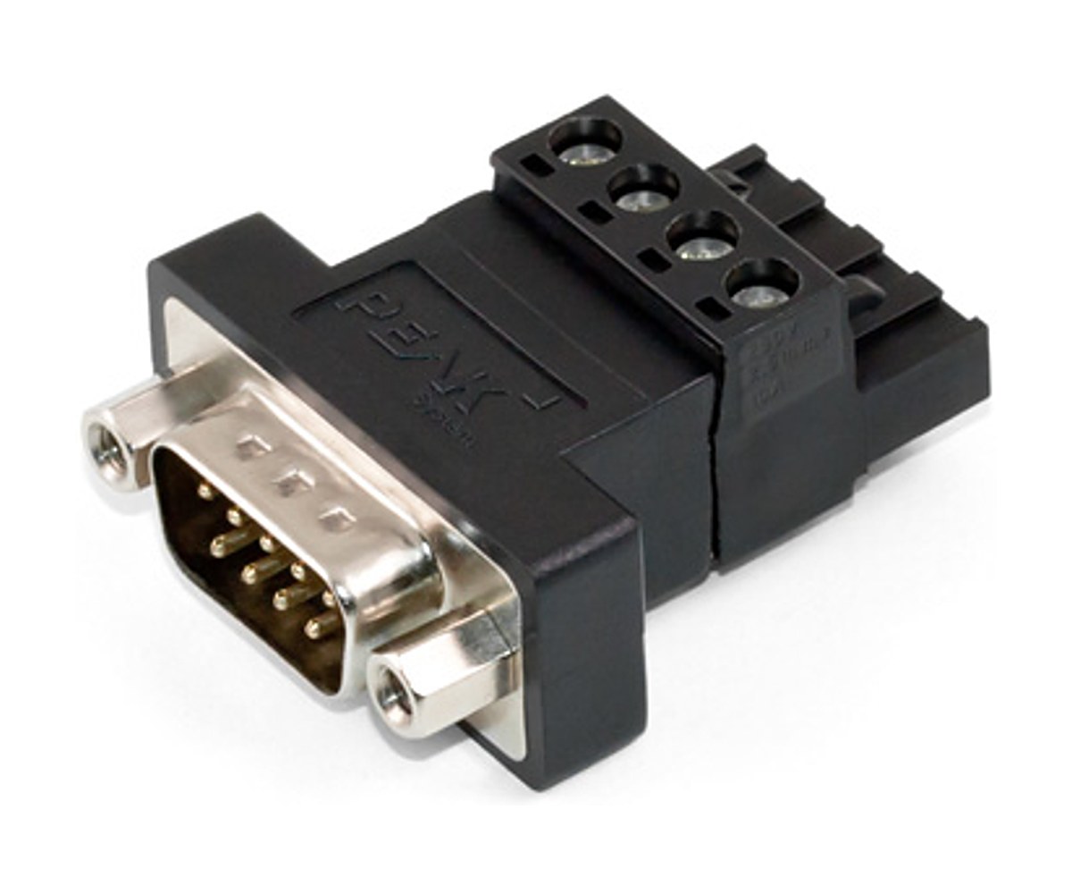
PCAN-Adapter D-Sub to Screw Terminals

PCAN-Adapter D-Sub to Screw Terminals

Connect bare CAN wires to a standard D-Sub socket

Wiring harnesses and test benches often end in loose CAN wires instead of a connector. This adapter takes those wires on a 3-pin screw terminal block and puts them on a 9-pin D-Sub socket, so you can make up custom connections quickly. The socket follows CiA 106, so the adapter is not limited to PEAK products.

If the bus needs termination at that point, you can fit your own resistor, SMD or wired, on the solder pads provided on the board.

Highlights

  • 3-pin Phoenix screw terminal to 9-pin D-Sub socket
  • D-Sub wired to CiA 106
  • For open cable ends
  • Solder pads for an optional SMD or wired termination resistor

Key Specifications

SpecValue
Order numberIPEK-003025
Connectors3-pin screw terminal (Phoenix) to 9-pin D-Sub socket (CiA 106)
UseConnecting open CAN cable ends
TerminationNot fitted. Solder pads for an SMD or wired resistor

In the Box

  • PCAN-Adapter D-Sub to Screw Terminals

An alternative from Ixxat is the Ixxat CAN Adapter Screw Terminals to D-Sub 9. For PEAK DIN rail devices, use the PCAN-Adapter D-Sub for DR Products. To terminate a D-Sub bus without soldering, use the PCAN-Term.

For quantities, lead time or a quote, contact Pertech.

PCAN-MicroMod FD ECU Adapter

PCAN-MicroMod FD ECU Adapter

Screw terminal wiring for the PCAN-MicroMod FD ECU on the bench

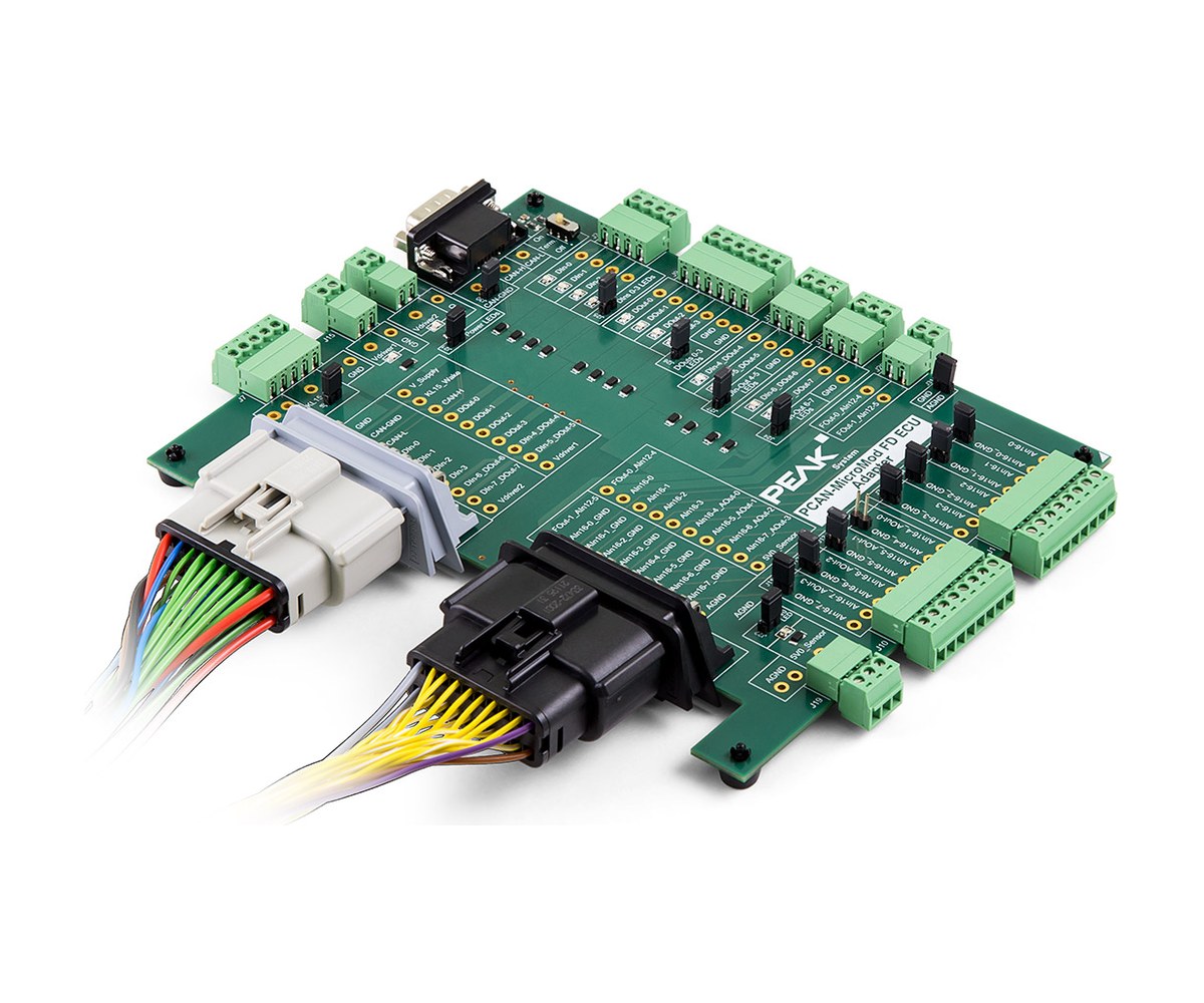
The PCAN-MicroMod FD ECU Adapter makes it easy to wire the PCAN-MicroMod FD ECU while you develop and validate a configuration. A color-coded cable set connects the ECU automotive connectors (Molex MX150) to the board, which brings every signal group out on Phoenix screw terminals and the CAN bus on a 9-pin D-Sub socket.

LEDs show the state of the digital I/Os, the supply and the 5 V output. Jumpers can disconnect the LEDs to save current and can tie each analog input ground to the module ground.

Highlights

  • Molex MX150 to Phoenix screw terminals
  • Color-coded cable set to the ECU included
  • CAN on a 9-pin D-Sub socket (CiA 106)
  • Switchable 120 ohm CAN termination
  • Status LEDs, detachable by jumper

Screw terminal groups

  • Power supply and wake-up
  • Supply for the high-side switches
  • Analog I/Os
  • Digital I/Os
  • Frequency outputs (low-side)
  • 5 V output for sensor supply

Key Specifications

SpecValue
Order numberIPEH-003086
ForPCAN-MicroMod FD ECU
ECU sideMolex MX150 automotive connectors, via cable set
Board sidePhoenix screw terminal strips
CAN9-pin D-Sub socket (CiA 106), switchable 120 ohm termination
LEDsDigital I/Os, power supply, 5 V output
JumpersLED disconnect, analog ground to AGND

In the Box

  • PCAN-MicroMod FD ECU Adapter
  • Pre-configured, color-coded cable set for board and ECU

It is made for the PCAN-MicroMod FD ECU.

For quantities, lead time or a quote, contact Pertech.

PEAK-DevPack Debug Adapter

PEAK-DevPack Debug Adapter

Connect a hardware debugger to programmable PCAN hardware

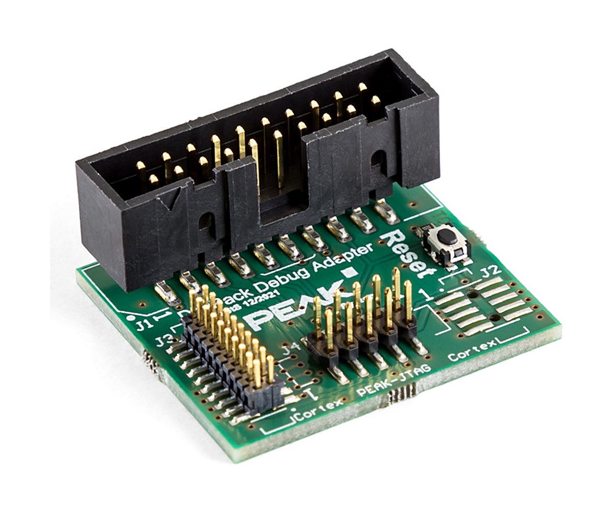
The PEAK-DevPack Debug Adapter links a hardware debugger to the JTAG connector of the ARM-based, programmable PEAK products. Several connectors and three ribbon cables match the different JTAG headers on those devices.

A reset button restarts the device you are programming, so you do not have to unplug it during a debug session.

Highlights

  • Hardware debugger to PCAN hardware JTAG
  • Three ribbon cables for different header pitches
  • Reset button for the target
  • Covers six programmable PEAK products

Supported PEAK hardware

  • PCAN-Router Pro FD (IPEH-002220, IPEH-002222)
  • PCAN-Router FD (IPEH-002214, IPEH-002215)
  • PCAN-MicroMod FD (IPEH-003080)
  • PCAN-GPS (IPEH-002110)
  • PCAN-GPS FD (IPEH-003110)
  • PCAN-RS-232 FD (IPEH-003120)

Key Specifications

SpecValue
Order numberIPEK-003026
FunctionAdapter from a hardware debugger to the JTAG connector of PCAN hardware
Ribbon cables20-pin 2.54 mm, 20-pin 1.27 mm, 10-pin 2 mm
ControlsReset button for the target

In the Box

  • PEAK-DevPack Debug Adapter
  • Ribbon cable, 20-pin, 2.54 mm pitch
  • Ribbon cable, 20-pin, 1.27 mm pitch
  • Ribbon cable, 10-pin, 2 mm pitch
  • Manual in PDF format

It supports the PCAN-Router Pro FD, PCAN-Router FD, PCAN-MicroMod FD, PCAN-GPS FD and PCAN-RS-232 FD.

For quantities, lead time or a quote, contact Pertech.

PCAN-Cable 1 & 2

PCAN-Cable 1 & 2

Shielded D-Sub cables for building CAN and CAN FD buses

PCAN-Cable 1 and PCAN-Cable 2 are made for wiring a CAN bus. Both are 2 m long and have a 9-pin D-Sub socket at each end, with the shield tied to ground.

PCAN-Cable 2 has 120-ohm termination resistors built in. That makes it the quick choice for linking two High-speed CAN nodes with nothing else on the bus. PCAN-Cable 1 has no termination. Use it for a longer bus that has tap points and separate terminators, such as the PCAN-T-Adapter and PCAN-Term. Both cables also work on CAN FD buses.

Highlights

  • 9-pin D-Sub socket at both ends, wired to CiA 106
  • 2.0 m length, shield connected to GND
  • Cable 1 without termination, Cable 2 with 120-ohm termination
  • Usable on CAN FD buses

Versions and order numbers

  • IPEK-003000: PCAN-Cable 1, no termination resistors
  • IPEK-003001: PCAN-Cable 2, with 120-ohm termination resistors

Key Specifications

SpecValue
Order numbersIPEK-003000, IPEK-003001
Connectors9-pin D-Sub socket at both ends (CiA 106)
Length2.0 m
ShieldConnected to GND
TerminationCable 1: none. Cable 2: 120-ohm resistors
CAN FDSuitable

In the Box

  • PCAN-Cable 1 or PCAN-Cable 2, in the version ordered

To build out a bus, add the PCAN-T-Adapter for tap points and the PCAN-Term at the ends. The cables connect to PEAK interfaces such as the PCAN-USB FD. For measuring gear, see PCAN-Cable 3.

For quantities, lead time or a quote, contact Pertech.

PCAN-Cable 3

PCAN-Cable 3

CAN-High and CAN-Low on banana plugs for your measuring gear

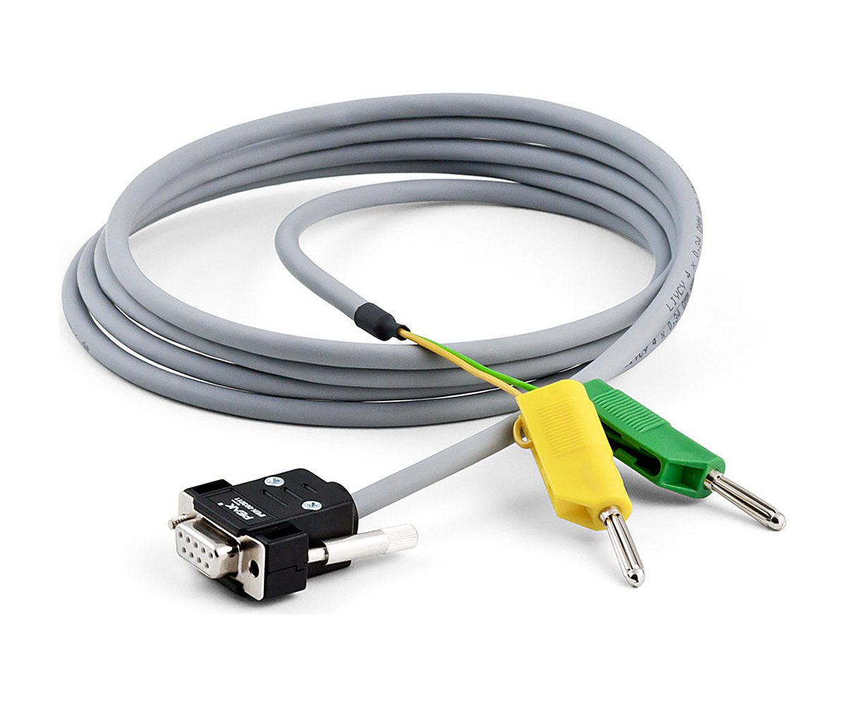
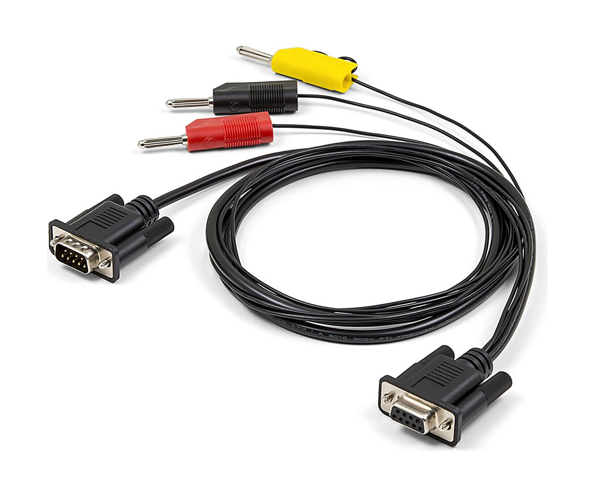
PCAN-Cable 3 takes the two halves of the differential CAN signal, CAN-High and CAN-Low, from a CAN bus or straight from a CAN interface and brings them out on 4 mm banana plugs. That makes it quick to hook a bus up to an oscilloscope or other test and measurement equipment.

It has no termination resistors and works on CAN FD buses too. PEAK has sold a slightly modified version of the cable since the end of 2023.

Highlights

  • 9-pin D-Sub socket wired to CiA 106
  • CAN-High and CAN-Low on 4 mm banana plugs
  • No termination resistors
  • Usable on CAN FD buses

Key Specifications

SpecValue
Order numberIPEK-003011
Connectors9-pin D-Sub socket (CiA 106) to 4 mm banana plugs
SignalsCAN-High, CAN-Low
Length2.0 m
TerminationNone

In the Box

  • PCAN-Cable 3

It plugs into PEAK CAN interfaces such as the PCAN-USB FD. Other CAN cables: PCAN-Cable 1 & 2 and PCAN-Cable M12.

For quantities, lead time or a quote, contact Pertech.

LIN Connection Cable for PCAN-LIN

LIN Connection Cable for PCAN-LIN

Separate access to LIN, supply and CAN on the PCAN-LIN module

The PCAN-LIN module brings CAN, LIN and its power supply out on a single D-Sub connector. When you need to reach the LIN side separately, this cable splits the lines: LIN and the LIN supply end in 4 mm banana plugs, and the CAN lines continue to a 9-pin D-Sub plug.

There is no terminating resistor in the cable, and it can be used on CAN FD buses. It does not suit the PEAK PC LIN interfaces, which have their own cable.

Highlights

  • Made for the PCAN-LIN module
  • LIN on a 4 mm banana plug
  • LIN supply on 4 mm banana plugs
  • CAN forwarded to a 9-pin D-Sub plug
  • Usable on CAN FD buses

Key Specifications

SpecValue
Order numberIPEK-003008
ForPCAN-LIN
CAND-Sub plug, 9-pin
LIN and LIN supplyBanana plugs, 4 mm
LengthAbout 1.00 m
TerminationNone

In the Box

  • LIN Connection Cable for PCAN-LIN

It is made for the PCAN-LIN. For the PC LIN interfaces, use the LIN Connection Cable for PC LIN Interfaces.

For quantities, lead time or a quote, contact Pertech.

LIN Connection Cable for PC LIN Interfaces

LIN Connection Cable for PC LIN Interfaces

Break out the LIN, supply and CAN lines of a PC LIN interface

On the PCAN-USB Pro FD and the PCAN-USB Pro, CAN and LIN share one D-Sub connector, and the PLIN-USB also reaches the LIN bus through a D-Sub. This cable splits those lines so you can reach the LIN side on its own: LIN and the LIN supply come out on 4 mm banana plugs, while the CAN lines carry on to a 9-pin D-Sub plug.

The cable has no terminating resistor and works on CAN FD buses as well. It is not meant for the PCAN-LIN module, which has its own cable.

Highlights

  • Made for PCAN-USB Pro FD, PCAN-USB Pro and PLIN-USB
  • LIN on a 4 mm banana plug
  • LIN supply on 4 mm banana plugs
  • CAN forwarded to a 9-pin D-Sub plug
  • Usable on CAN FD buses

Key Specifications

SpecValue
Order numberIPEK-003013
ForPCAN-USB Pro FD, PCAN-USB Pro, PLIN-USB
CAND-Sub plug, 9-pin
LIN and LIN supplyBanana plugs, 4 mm
LengthAbout 0.75 m
TerminationNone

In the Box

  • LIN Connection Cable for PC LIN Interfaces

It fits the PCAN-USB Pro FD and the PLIN-USB. For the PCAN-LIN module, use the LIN Connection Cable for PCAN-LIN.

For quantities, lead time or a quote, contact Pertech.

PCAN-Cable OBD-2

PCAN-Cable OBD-2

Reach the CAN lines of a vehicle OBD-2 port with a PEAK interface

Most current cars have an OBD-2 port where diagnostic and test equipment plugs in. PCAN-Cable OBD-2 brings the CAN signals from that port to a 9-pin D-Sub socket, so a PEAK CAN interface can connect to the vehicle directly.

As supplied, only pins 6 and 14 of the OBD-2 plug carry signals: CAN-High and CAN-Low per J-2284. All OBD-2 contacts are fitted in the plug, so you can wire other pins yourself if your setup needs them.

Highlights

  • OBD-2 plug to 9-pin D-Sub socket (CiA 106)
  • CAN-High on pin 6, CAN-Low on pin 14 (J-2284)
  • All OBD-2 contacts fitted, free to assign
  • 1.0 m length, no termination resistors

Key Specifications

SpecValue
Order numberIPEK-003004
Vehicle sideOBD-2 connector, all pins fitted
OBD-2 pin assignmentPin 6: CAN-High (J-2284). Pin 14: CAN-Low (J-2284). Other pins not assigned
Interface side9-pin D-Sub socket (CiA 106)
Length1.0 m
TerminationNone

In the Box

  • PCAN-Cable OBD-2

It suits PEAK CAN interfaces such as the PCAN-USB and PCAN-USB FD. For heavy-duty vehicles with a DEUTSCH diagnostic port, see the PCAN-Cable J1939.

For quantities, lead time or a quote, contact Pertech.

PCAN-Cable J1939

PCAN-Cable J1939

Reach a J1939 DEUTSCH diagnostic connector with a PEAK CAN interface

Heavy-duty vehicles such as construction machines, tractors and farm machinery use SAE J1939 messages over CAN, and their diagnostic port is often a rugged DEUTSCH connector. PCAN-Cable J1939 wires the CAN lines of that connector to D-Sub sockets, so you can connect a PEAK CAN interface directly.

Four versions cover the type 1 and type 2 DEUTSCH connectors, each with one or two D-Sub sockets.

Highlights

  • 9-pole DEUTSCH HD connector (J1939 type 1 or type 2)
  • 9-pin D-Sub socket wired to CiA 106
  • Versions with one or two D-Sub sockets
  • No termination resistor

Versions and order numbers

  • IPEK-003009: type 1 DEUTSCH connector to D-Sub
  • IPEK-003019: type 2 DEUTSCH connector to D-Sub
  • IPEK-003014: type 1 DEUTSCH connector to 2 x D-Sub
  • IPEK-003015: type 2 DEUTSCH connector to 2 x D-Sub

Key Specifications

SpecValue
Order numbersIPEK-003009, IPEK-003019, IPEK-003014, IPEK-003015
Vehicle side9-pole DEUTSCH connector, HD series, J1939 type 1 or 2
Interface side9-pin D-Sub socket (CiA 106), one or two
Length1.0 m
TerminationNone

In the Box

  • PCAN-Cable J1939 in the version ordered

It suits PEAK CAN interfaces such as the PCAN-USB. For passenger-car diagnostic ports, see the PCAN-Cable OBD-2.

For quantities, lead time or a quote, contact Pertech.

PCAN-Cable M12

PCAN-Cable M12

Connect PEAK CAN interfaces to M12 and NMEA 2000 networks

M12 circular connectors are rugged and well protected against the environment, so they are a common way to connect to CAN in harsh conditions. The NMEA 2000 standard for CAN on boats and ships also calls for M12 connectors.

PCAN-Cable M12 wires the CAN lines of a 9-pin D-Sub socket to a 5-pin M12 connector and adds the shield and supply lines that NMEA 2000 defines. A PEAK CAN interface can then connect directly to such a network.

Highlights

  • 9-pin D-Sub socket to 5-pin M12 connector
  • Pinout to CiA 106 and NMEA 2000
  • Shield and supply lines per NMEA 2000
  • No termination resistor
  • Usable on CAN FD buses

Key Specifications

SpecValue
Order numberIPEK-003016
Connectors9-pin D-Sub socket to 5-pin M12 circular connector
StandardsCiA 106, NMEA 2000
Length1.0 m
TerminationNone

In the Box

  • PCAN-Cable M12

It suits PEAK CAN interfaces such as the PCAN-USB FD. See also PCAN-Cable 3 and PCAN-Cable J1939.

For quantities, lead time or a quote, contact Pertech.

PAE-Cable H-MTD

PAE-Cable H-MTD

Shielded Single-Pair Ethernet link between two H-MTD ports

The PAE-Cable H-MTD connects two Automotive Ethernet devices that have H-MTD ports, such as the PAE-Media Converter and a vehicle control unit. H-MTD is a small, high-frequency connector for Single-Pair Ethernet in cars and, together with MATEnet, one of the two main SPE connector types in current vehicle networks.

The 2 m cable is shielded and carries 100BASE-T1 and 1000BASE-T1 links.

Highlights

  • H-MTD socket (jack) at each end
  • Shielded cable, type GG 2Speed 251
  • For 100BASE-T1 and 1000BASE-T1
  • 2.0 m long

Key Specifications

SpecValue
Order numberIPEK-100001
Connectors2 x H-MTD socket (jack)
CableShielded, type GG 2Speed 251
Length2.0 m
Ethernet100BASE-T1 and 1000BASE-T1

In the Box

  • PAE-Cable H-MTD

It is made for the PAE-Media Converter. For MATEnet ports, use the PAE-Cable MATEnet.

For quantities, lead time or a quote, contact Pertech.

PAE-Cable MATEnet

PAE-Cable MATEnet

Shielded Single-Pair Ethernet link between two MATEnet ports

The PAE-Cable MATEnet joins two Automotive Ethernet devices with MATEnet ports, for example the PAE-Media Converter and an ECU on the test bench. MATEnet is a standard SPE connector system from TE Connectivity, common for 100BASE-T1 and 1000BASE-T1 in vehicle networks and test setups.

The cable is shielded and 2 m long.

Highlights

  • MATEnet socket (female) at each end
  • Shielded cable, type GG 2Speed 251
  • For 100BASE-T1 and 1000BASE-T1
  • 2.0 m long

Key Specifications

SpecValue
Order numberIPEK-100002
Connectors2 x MATEnet socket (female)
CableShielded, type GG 2Speed 251
Length2.0 m
Ethernet100BASE-T1 and 1000BASE-T1

In the Box

  • PAE-Cable MATEnet

It is made for the PAE-Media Converter. For H-MTD ports, use the PAE-Cable H-MTD.

For quantities, lead time or a quote, contact Pertech.

MICSIG SigOFIT Gen 3 Optical-Fiber Isolated Probe (MOIP)

The MICSIG SigOFIT Gen 3 (MOIP series) is an optical-fiber isolated probe from 200 MHz to 1.2 GHz with an 85 kVpk common-mode voltage range, CMRR of 180 dB at DC and 106 dB at 1.2 GHz, 1% DC gain accuracy and noise as low as 0.3 mVrms. A laser carries both the signal and the power over fiber, so the probe head needs no battery and can run 24/7. It is built for measuring fast high-side signals on GaN, SiC and IGBT power stages. Pertech, the exclusive MICSIG distributor in Israel, quotes in ILS with local invoicing, handles warranty in Israel and arranges calibration and repair.

SigOFIT Gen 3 highlights

  • Bandwidth 200MHz to 1.2GHz, rise time down to <=350ps
  • Common mode voltage range 85kVpk
  • CMRR 180dB at DC, 128dB at 100MHz, 106dB at 1.2GHz
  • DC gain accuracy 1%, noise as low as 0.3mVrms
  • Differential range from +/-10 V to +/-5000 V with interchangeable attenuator tips
  • Laser transmits signal and power over fiber, no batteries, 24/7 continuous testing
  • Real-time optical power compensation, no manual calibration during testing
  • Input capacitance as low as 1pF, short coaxial leads for GaN testing
  • AutoZero in less than 1 second; universal BNC for all oscilloscope brands

Models

ModelBandwidthRise timeCmrr at bwNoise
MOIP1200P1.2GHz<=350ps106dB @ 1.2GHz0.45mVrms
MOIP1000P1GHz<=450ps108dB @ 1GHz0.45mVrms
MOIP500P500MHz<=800ps114dB @ 500MHz0.3mVrms
MOIP350P350MHz<=1ns118dB @ 350MHz0.3mVrms
MOIP200P200MHz<=1.5ns122dB @ 200MHz0.3mVrms

Where the SigOFIT Gen 3 fits

  • Motor drive, power converter and electronic ballast design
  • GaN, SiC, IGBT half/full bridge design
  • Inverter, UPS and switching power supply design
  • High voltage, high bandwidth safety test
  • Power device evaluation
  • Current shunt measurements
  • EMI and ESD troubleshooting
  • Floating measurements

Key Specifications

SpecValue
Bandwidth200MHz / 350MHz / 500MHz / 1GHz / 1.2GHz
Rise time<=1.5ns to <=350ps
CMRRDC: 180dB; 122dB @ 200MHz to 106dB @ 1.2GHz
Differential voltage range+/-10 V (OP20) to +/-5000 V (OP10000), by tip
Attenuator tipsOP20, OP50, OP100 (MMCX); OP200, OP500, OP1000, OP2000, OP5000 (MCX); OP10000 (LCX)
Noise0.3mVrms (200-500MHz) / 0.45mVrms (1GHz, 1.2GHz)
DC gain accuracy1%
Common mode voltage range85kVpk
Input capacitanceAs low as 1pF
InterfaceUniversal BNC, compatible with all oscilloscope brands

Standard and optional tips: Standard tips: OP50 (+/-25V) and OP5000 (+/-2500V) on MOIP1200P/1000P/500P/350P; on MOIP200P only OP50 is standard and OP5000 is optional. All other tips (OP20, OP100, OP200, OP500, OP1000, OP2000, OP10000) are optional.

SigOFIT Gen 3 vs Tektronix IsoVu and Keysight PS0008A

On the makers’ own published figures, SigOFIT Gen 3 offers more bandwidth, a higher common-mode range, stronger common-mode rejection at high frequency and twice the differential range of the Tektronix IsoVu and Keysight PS0008A optically isolated probes.

And it costs a fraction of the price of those probes. Ask Pertech, the exclusive MICSIG distributor in Israel, for a quote in ILS.

SigOFIT Gen 3 compared with Tektronix IsoVu and Keysight PS0008A, published specifications
SpecificationMICSIG SigOFIT Gen 3Tektronix IsoVu Gen 2 (TIVP)Keysight PS0008A
Maximum bandwidth1.2 GHz1 GHz1 GHz
Common-mode voltage range85 kVpk+/-60 kV+/-60 kV
CMRR at DC180 dB160 dBover 180 dB
CMRR at 100 MHz128 dB100 dB65 dB
CMRR at 1 GHz108 dB (1 GHz model)not published54 dB
Maximum differential range+/-5000 V+/-2500 V+/-2500 V

Figures as published by each manufacturer, read on 07/11/2026: micsig.com (SigOFIT Gen 3, MOIP series), tek.com (IsoVu isolated voltage probes, TIVP series), and the Keysight PS00xxA data sheet (CMRR with the PS0017A tip, Keysight’s highest-CMRR tip). Test conditions and tips differ between makers; check each data sheet for your measurement.

MICSIG SigOFIT Gen 3 in Israel

Buy the SigOFIT Gen 3 from Pertech, the exclusive MICSIG distributor in Israel: quotes in ILS and local invoicing, warranty handled in Israel, calibration and repair arranged through Pertech, some models in stock in Israel, and technical support from Pertech engineers.

Frequently asked questions

How does SigOFIT compare with Tektronix IsoVu and Keysight isolated probes?

On the makers’ published figures, SigOFIT Gen 3 reaches 1.2 GHz (IsoVu and Keysight PS0008A: 1 GHz), handles 85 kVpk common mode (both others: +/-60 kV), keeps 128 dB CMRR at 100 MHz (IsoVu: 100 dB; PS0008A: 65 dB with its best tip) and measures up to +/-5000 V differential (both others: +/-2500 V).

Is SigOFIT less expensive than Tektronix IsoVu or Keysight?

Yes. SigOFIT costs a fraction of the price of the Tektronix IsoVu and Keysight PS0008A isolated probes, while offering higher published specifications. Pertech, the exclusive MICSIG distributor in Israel, quotes in ILS.

What is the MICSIG SigOFIT Gen 3?

The MICSIG SigOFIT Gen 3 (MOIP series) is an optical-fiber isolated probe from 200 MHz to 1.2 GHz with an 85 kVpk common-mode voltage range, CMRR of 180 dB at DC and 106 dB at 1.2 GHz, 1% DC gain accuracy and noise as low as 0.3 mVrms. A laser carries both the signal and the power over fiber, so the probe head needs no battery and can run 24/7. It is built for measuring fast high-side signals on GaN, SiC and IGBT power stages.

Where can I buy the MICSIG SigOFIT Gen 3 in Israel?

From Pertech, the exclusive MICSIG distributor in Israel. Contact Pertech for a quote in ILS, availability and help choosing the model.

Who handles warranty and calibration in Israel?

Pertech handles MICSIG warranty in Israel: you return the unit to Pertech and Pertech deals with MICSIG. Pertech also arranges calibration and repair.

Does the SigOFIT Gen 3 work with any oscilloscope?

MICSIG specifies a standard BNC output for the SigOFIT Gen 3, compatible with oscilloscopes from other brands as well as MICSIG’s own.

Can Pertech help me set it up?

Yes. Pertech engineers help with setup and application questions for MICSIG instruments bought through Pertech.

Related MICSIG products at Pertech

Need a quote for the MICSIG SigOFIT Gen 3? Contact Pertech.


MICSIG RCP Series Rogowski AC Current Probe

The MICSIG RCP series are Rogowski AC current probes with peak currents from 60 Apk to 12000 Apk, bandwidth up to 30 MHz and di/dt up to 70 kA/us. Coils come in four cross-sections, from 1.6 mm (XS) to 8.0 mm (L), so they reach transistor pins and busbars alike. Pertech, the exclusive MICSIG distributor in Israel, quotes in ILS with local invoicing, handles warranty in Israel and arranges calibration and repair.

RCP series highlights

  • AC current up to 12000Apk
  • Bandwidth up to 30MHz (XS-80 coils), low end down to 2Hz
  • Peak di/dt up to 70kA/μs
  • Coil isolation up to 10kVpk (L series)
  • Nearly zero insertion impedance, minimal interference to the circuit under test
  • Coil cross-section from 1.6mm (XS) to 8.0mm (L) for hard-to-reach parts
  • Customizable coil cross-section diameter, perimeter and lead length
  • Typical accuracy 2%
  • Standard BNC interface, compatible with all oscilloscope brands

Models

ModelPeak currentBandwidthSensitivity
RCP60XS-8060Apk70Hz-30MHz100mV/A
RCP120XS-80120Apk34Hz-30MHz50mV/A
RCP300XS-80300Apk10Hz-30MHz20mV/A
RCP600XS-80600Apk8Hz-30MHz10mV/A
RCP1200XS-801200Apk5Hz-30MHz5mV/A
RCP3000XS-803000Apk4Hz-30MHz2mV/A
RCP6000XS-806000Apk4Hz-30MHz1mV/A
RCP12000XS-8012000Apk2Hz-30MHz0.5mV/A
RCP300XS-200300Apk14Hz-20MHz20mV/A
RCP600XS-200600Apk7Hz-20MHz10mV/A
RCP1200XS-2001200Apk5Hz-20MHz5mV/A
RCP6000XS-2006000Apk3Hz-20MHz1mV/A
RCP120S-200120Apk14Hz-25MHz50mV/A
RCP300S-200300Apk7Hz-25MHz20mV/A
RCP600S-200600Apk5Hz-25MHz10mV/A
RCP1200S-2001200Apk5Hz-25MHz5mV/A
RCP3000S-2003000Apk3Hz-25MHz2mV/A
RCP6000S-2006000Apk2Hz-25MHz1mV/A
RCP6000S-7006000Apk3Hz-10MHz1mV/A
RCP12000S-70012000Apk2Hz-10MHz0.5mV/A
RCP120M-200120Apk14Hz-25MHz50mV/A
RCP300M-200300Apk7Hz-25MHz20mV/A
RCP600M-200600Apk5Hz-25MHz10mV/A
RCP1200M-2001200Apk5Hz-25MHz5mV/A
RCP3000M-2003000Apk3Hz-25MHz2mV/A
RCP6000M-2006000Apk2Hz-25MHz1mV/A
RCP6000M-7006000Apk3Hz-10MHz1mV/A
RCP12000M-70012000Apk2Hz-10MHz0.5mV/A
RCP600L-700600Apk8Hz-10MHz10mV/A
RCP1200L-7001200Apk6Hz-10MHz5mV/A
RCP3000L-7003000Apk4Hz-10MHz2mV/A
RCP6000L-7006000Apk3Hz-10MHz1mV/A
RCP12000L-70012000Apk2Hz-10MHz0.5mV/A

Where the RCP series fits

  • Motor drive current and power quality in VSD, UPS or SMPS circuits
  • Double-pulse testing of SiC and GaN MOSFET and IGBT pin currents
  • Load current and high-order harmonic current in power electronics
  • High frequency sinusoidal, pulsed or transient currents
  • AC currents in 3-phase supply systems
  • Power consumption in semiconductors
  • 50/60Hz power frequency current
  • Power converter development and diagnostics

Key Specifications

SpecValue
Peak current60Apk to 12000Apk
Bandwidth2Hz-10MHz to 70Hz-30MHz depending on model
Output sensitivity100mV/A (10X) to 0.5mV/A (2000X)
Peak di/dt4kA/μs to 70kA/μs
Coil cross-section diameter1.6mm (XS) / 3.0mm (S) / 4.5mm (M) / 8.0mm (L)
Coil circumference80mm (XS), 200mm (XS, S, M), 700mm (S, M, L)
Peak coil isolation voltage1.5kVpk (XS) / 3kVpk (S) / 5kVpk (M) / 10kVpk (L), coil part only
Accuracy (typical)2%
Cable length1.5m integrator to coil, customizable
Output impedance1MΩ
Power supplyDC 12V
InterfaceStandard BNC

MICSIG RCP series in Israel

Buy the RCP series from Pertech, the exclusive MICSIG distributor in Israel: quotes in ILS and local invoicing, warranty handled in Israel, calibration and repair arranged through Pertech, some models in stock in Israel, and technical support from Pertech engineers.

Frequently asked questions

What is the MICSIG RCP series?

The MICSIG RCP series are Rogowski AC current probes with peak currents from 60 Apk to 12000 Apk, bandwidth up to 30 MHz and di/dt up to 70 kA/us. Coils come in four cross-sections, from 1.6 mm (XS) to 8.0 mm (L), so they reach transistor pins and busbars alike.

Where can I buy the MICSIG RCP series in Israel?

From Pertech, the exclusive MICSIG distributor in Israel. Contact Pertech for a quote in ILS, availability and help choosing the model.

Who handles warranty and calibration in Israel?

Pertech handles MICSIG warranty in Israel: you return the unit to Pertech and Pertech deals with MICSIG. Pertech also arranges calibration and repair.

Does the RCP series work with any oscilloscope?

MICSIG specifies a standard BNC output for the RCP series, compatible with oscilloscopes from other brands as well as MICSIG’s own.

Can Pertech help me set it up?

Yes. Pertech engineers help with setup and application questions for MICSIG instruments bought through Pertech.

Related MICSIG products at Pertech

Need a quote for the MICSIG RCP series? Contact Pertech.
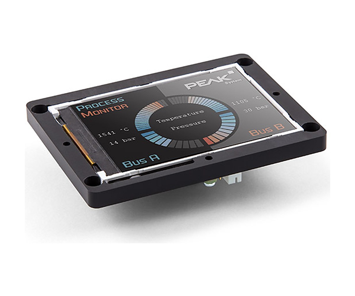

MICSIG ACP1000 AC Current Clamp Probe

The MICSIG ACP1000 is a clamp-on AC current probe from 10 Hz to 100 kHz with three ranges, 10 A, 100 A and 1000 A, and accuracy of 1% on the 1000 A range. It clamps around the conductor, so the circuit stays connected. Pertech, the exclusive MICSIG distributor in Israel, quotes in ILS with local invoicing, handles warranty in Israel and arranges calibration and repair.

ACP1000 highlights

  • Current range up to 1000A
  • Operating frequency 10Hz to 100kHz
  • Accuracy up to 1% (1000A range)
  • Three ranges: 10A, 100A, 1000A
  • Clamp design, no need to disconnect the circuit under test
  • BNC interface
  • Premium, durable material; simple and safe to use

Models

ModelInputOutputAccuracy
ACP1000 (10A range)0.1-10A100mV/A3% +/-10mV
ACP1000 (100A range)0.1-100A10mV/A2% +/-5mV
ACP1000 (1000A range)1-1000A1mV/A1% +/-1mV

Where the ACP1000 fits

  • Current and electrical energy measurement
  • Power factor correction devices
  • Motor drivers
  • Inverters and converters
  • Industrial control devices
  • Oscilloscopes and harmonic analyzers
  • Aviation electronic equipment

Key Specifications

SpecValue
Frequency10Hz-100kHz
Input ranges0.1-10A / 0.1-100A / 1-1000A
Rated output100mV/A / 10mV/A / 1mV/A
Accuracy grade3% +/-10mV / 2% +/-5mV / 1% +/-1mV
Rated burden>=100kΩ
InterfaceBNC

MICSIG ACP1000 in Israel

Buy the ACP1000 from Pertech, the exclusive MICSIG distributor in Israel: quotes in ILS and local invoicing, warranty handled in Israel, calibration and repair arranged through Pertech, some models in stock in Israel, and technical support from Pertech engineers.

Frequently asked questions

What is the MICSIG ACP1000?

The MICSIG ACP1000 is a clamp-on AC current probe from 10 Hz to 100 kHz with three ranges, 10 A, 100 A and 1000 A, and accuracy of 1% on the 1000 A range. It clamps around the conductor, so the circuit stays connected.

Where can I buy the MICSIG ACP1000 in Israel?

From Pertech, the exclusive MICSIG distributor in Israel. Contact Pertech for a quote in ILS, availability and help choosing the model.

Who handles warranty and calibration in Israel?

Pertech handles MICSIG warranty in Israel: you return the unit to Pertech and Pertech deals with MICSIG. Pertech also arranges calibration and repair.

Does the ACP1000 work with any oscilloscope?

MICSIG specifies a standard BNC output for the ACP1000, compatible with oscilloscopes from other brands as well as MICSIG’s own.

Can Pertech help me set it up?

Yes. Pertech engineers help with setup and application questions for MICSIG instruments bought through Pertech.

Related MICSIG products at Pertech

Need a quote for the MICSIG ACP1000? Contact Pertech.
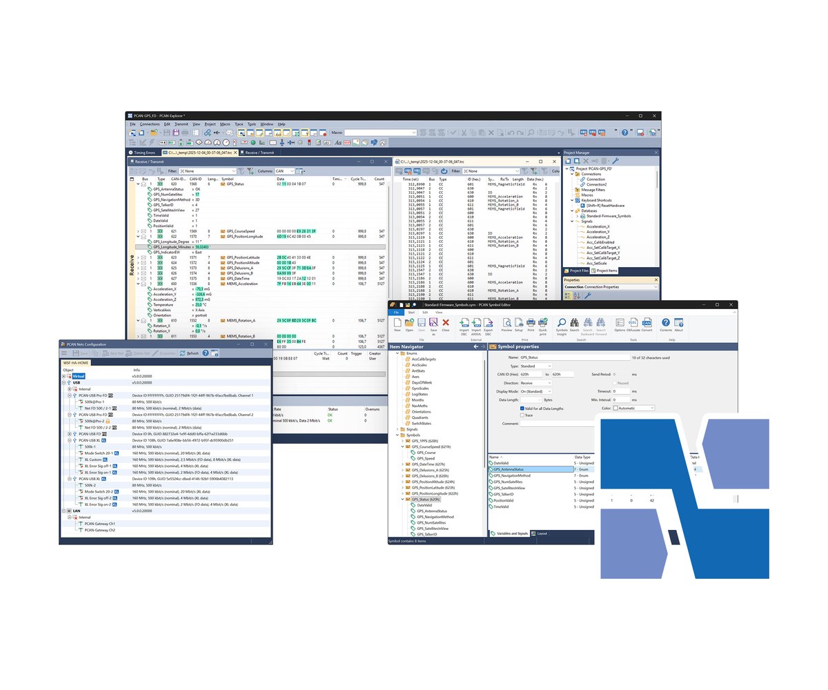

MICSIG CP2100 Low-Frequency AC/DC Current Probe

The MICSIG CP2100 is a low-frequency AC/DC current probe with 10 A and 100 A ranges, up to 100 Apk, and DC to 800 kHz (CP2100A) or DC to 2.5 MHz (CP2100B). It takes its power from the oscilloscope’s USB port and fits conductors up to 13 mm. Pertech, the exclusive MICSIG distributor in Israel, quotes in ILS with local invoicing, handles warranty in Israel and arranges calibration and repair.

CP2100 highlights

  • Bandwidth up to DC-2.5MHz (CP2100B)
  • Max. measurable current 100Apk (70.7Arms)
  • Two ranges: 10A (0.1V/A) and 100A (0.01V/A)
  • Powered directly from the oscilloscope USB port, no extra adapter
  • Auto and manual zero function
  • Split design, small appearance
  • Overload alarm: buzzer beeps and button flashes
  • Compatible with all BNC oscilloscopes; adapters also work with multimeters

Models

ModelBandwidthRise timeRanges
CP2100ADC-800kHz<=437.5ns10A / 100A
CP2100BDC-2.5MHz<=140ns10A / 100A

Where the CP2100 fits

  • Motor drives
  • Industrial frequency
  • Inverters
  • Power supplies
  • Avionics

Key Specifications

SpecValue
BandwidthDC-800kHz (A) / DC-2.5MHz (B)
Rise time<=437.5ns (A) / <=140ns (B)
Output sensitivity0.1V/A (10A) / 0.01V/A (100A)
DC accuracy (typical)3% +/-50mA (10A); 4% +/-50mA (100A, 500mA-40Apk); 15% (100A, 40Apk-100Apk)
Current measurement range50mA-10Apk (10A) / 1A-100Apk (100A)
Max. measuring current100Apk, 70.7Arms (DC+ACpk); 200Apk-pk, 70.7Arms (AC)
Signal delay100ns
Max. working / float voltageCAT III 300V, CAT II 600V
Max. conductor diameter13mm
Power supplyDC 5V (USB)
InterfaceUniversal BNC

MICSIG CP2100 in Israel

Buy the CP2100 from Pertech, the exclusive MICSIG distributor in Israel: quotes in ILS and local invoicing, warranty handled in Israel, calibration and repair arranged through Pertech, some models in stock in Israel, and technical support from Pertech engineers.

Frequently asked questions

What is the MICSIG CP2100?

The MICSIG CP2100 is a low-frequency AC/DC current probe with 10 A and 100 A ranges, up to 100 Apk, and DC to 800 kHz (CP2100A) or DC to 2.5 MHz (CP2100B). It takes its power from the oscilloscope’s USB port and fits conductors up to 13 mm.

Where can I buy the MICSIG CP2100 in Israel?

From Pertech, the exclusive MICSIG distributor in Israel. Contact Pertech for a quote in ILS, availability and help choosing the model.

Who handles warranty and calibration in Israel?

Pertech handles MICSIG warranty in Israel: you return the unit to Pertech and Pertech deals with MICSIG. Pertech also arranges calibration and repair.

Does the CP2100 work with any oscilloscope?

MICSIG specifies a standard BNC output for the CP2100, compatible with oscilloscopes from other brands as well as MICSIG’s own.

Can Pertech help me set it up?

Yes. Pertech engineers help with setup and application questions for MICSIG instruments bought through Pertech.

Related MICSIG products at Pertech

Need a quote for the MICSIG CP2100? Contact Pertech.
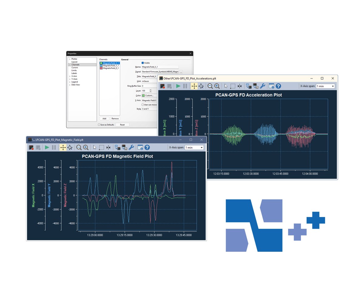

MICSIG CP Series High-Frequency AC/DC Current Probe

The MICSIG CP series are high-frequency AC/DC current probes in two groups: small-current models (5 A / 30 A ranges, DC to 150 MHz, 5 mm jaw) and high-current models up to 500 Arms / 750 Apk (DC to 10 MHz, 20 mm jaw), all with 1% typical accuracy, dual ranges and one-button degauss and auto-zero. Pertech, the exclusive MICSIG distributor in Israel, quotes in ILS with local invoicing, handles warranty in Israel and arranges calibration and repair.

CP series highlights

  • Bandwidth up to DC-150MHz (small current) and DC-10MHz (high current)
  • Up to 500Arms / 750Apk measurable current (CP5005)
  • Typical accuracy +/-1%, resolution down to 1mA (small current) or 10mA (high current)
  • Dual-range design for small-signal detection and high-current transients
  • Rise time down to <=2.67ns (CP1503B)
  • One-button auto degauss / auto-zero
  • Built-in overcurrent alarm for safe range switching
  • Standard BNC interface compatible with most oscilloscope brands
  • Jaw size 20mm (high current) or 5mm (small current)

Models

ModelBandwidthRangesMax currentJaw
CP5005DC-5MHz75A / 500A500Arms, 750Apk20mm
CP3008DC-8MHz50A / 300A300Arms, 500Apk20mm
CP3005DC-5MHz50A / 300A300Arms, 500Apk20mm
CP1510DC-10MHz30A / 150A150Arms, 300Apk20mm
CP1503BDC-150MHz5A / 30A30Arms, 50Apk5mm
CP1003BDC-100MHz5A / 30A30Arms, 50Apk5mm
CP503BDC-50MHz5A / 30A30Arms, 50Apk5mm

Where the CP series fits

  • Electric vehicle transportation design
  • Switching power supply design
  • Semiconductor devices design
  • Avionics design
  • Inverter/transformer design
  • Electronic ballast design
  • Industrial control / consumer electronics design
  • Power electronics and electric drive design

Key Specifications

SpecValue
BandwidthDC-5MHz to DC-150MHz
Rise time<=70ns (CP5005) to <=2.67ns (CP1503B)
Ranges5A/30A, 30A/150A, 50A/300A, 75A/500A
Max. current input30Arms/50Apk to 500Arms/750Apk
Accuracy (DC and 45-66Hz)+/-1% +/-1mA to +/-1% +/-100mA depending on range
Lowest measurable current1mA (5A range) to 100mA (high ranges)
Output sensitivity1V/1A (1X), 1V/10A (10X), 1V/100A (100X)
Overcurrent alarm>=7Apk (5A range) to >=500Apk (500A range)
Max. conductor diameter5mm (small current) / 20mm (high current)
Power supplyDC 12V
InterfaceUniversal BNC

MICSIG CP series in Israel

Buy the CP series from Pertech, the exclusive MICSIG distributor in Israel: quotes in ILS and local invoicing, warranty handled in Israel, calibration and repair arranged through Pertech, some models in stock in Israel, and technical support from Pertech engineers.

Frequently asked questions

What is the MICSIG CP series?

The MICSIG CP series are high-frequency AC/DC current probes in two groups: small-current models (5 A / 30 A ranges, DC to 150 MHz, 5 mm jaw) and high-current models up to 500 Arms / 750 Apk (DC to 10 MHz, 20 mm jaw), all with 1% typical accuracy, dual ranges and one-button degauss and auto-zero.

Where can I buy the MICSIG CP series in Israel?

From Pertech, the exclusive MICSIG distributor in Israel. Contact Pertech for a quote in ILS, availability and help choosing the model.

Who handles warranty and calibration in Israel?

Pertech handles MICSIG warranty in Israel: you return the unit to Pertech and Pertech deals with MICSIG. Pertech also arranges calibration and repair.

Does the CP series work with any oscilloscope?

MICSIG specifies a standard BNC output for the CP series, compatible with oscilloscopes from other brands as well as MICSIG’s own.

Can Pertech help me set it up?

Yes. Pertech engineers help with setup and application questions for MICSIG instruments bought through Pertech.

Related MICSIG products at Pertech

Need a quote for the MICSIG CP series? Contact Pertech.
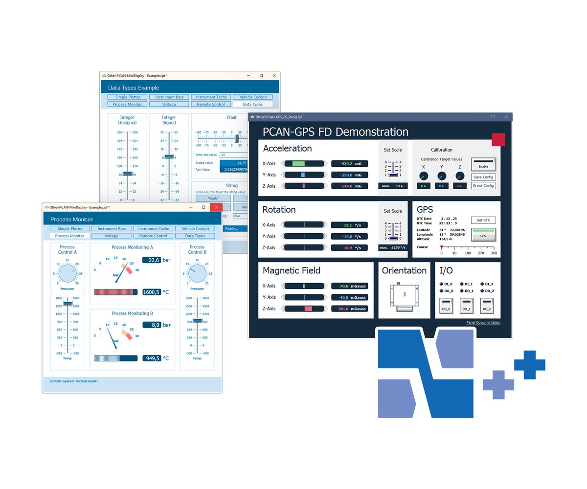

MICSIG VTO Android USB Oscilloscope

The MICSIG VTO is a 4-channel, 200 MHz oscilloscope (1 GSa/s, 50 Mpts) that works with an Android phone, tablet or PC over USB-C. It weighs 640 g, decodes CAN and LIN, and with the optional 7500 mAh battery runs field tests of up to 24 hours. Pertech, the exclusive MICSIG distributor in Israel, quotes in ILS with local invoicing, handles warranty in Israel and arranges calibration and repair.

VTO highlights

  • 200MHz bandwidth, 4 channels, 1GSa/s sampling
  • 50Mpts memory depth with Zoom
  • Works with any Android phone, tablet or PC via USB-C
  • 7500mAh battery (optional) for up to 24-hour field testing
  • 31 types of automated measurements
  • CAN and LIN serial bus decode
  • Power-off lock for secure transport
  • 640g net weight

Models

ModelBandwidthChannelsSamplingMemory
VTO2004200MHz41GSa/s50Mpts

Where the VTO fits

  • Field testing

Key Specifications

SpecValue
Bandwidth200MHz
Analog channels4
Rise time<=1.75ns
Real-time sampling rate1GSa/s
Memory depth50Mpts
Vertical resolution8bit
DC gain accuracy<=2%
Input impedance1MΩ +/-1% || 15pF
Power supplyDC 12V
Battery7.4V, 7500mAh Li-ion (optional)
Dimensions / weight140 x 215 x 52mm / 640g

MICSIG VTO in Israel

Buy the VTO from Pertech, the exclusive MICSIG distributor in Israel: quotes in ILS and local invoicing, warranty handled in Israel, calibration and repair arranged through Pertech, some models in stock in Israel, and technical support from Pertech engineers.

Frequently asked questions

What is the MICSIG VTO?

The MICSIG VTO is a 4-channel, 200 MHz oscilloscope (1 GSa/s, 50 Mpts) that works with an Android phone, tablet or PC over USB-C. It weighs 640 g, decodes CAN and LIN, and with the optional 7500 mAh battery runs field tests of up to 24 hours.

Where can I buy the MICSIG VTO in Israel?

From Pertech, the exclusive MICSIG distributor in Israel. Contact Pertech for a quote in ILS, availability and help choosing the model.

Who handles warranty and calibration in Israel?

Pertech handles MICSIG warranty in Israel: you return the unit to Pertech and Pertech deals with MICSIG. Pertech also arranges calibration and repair.

Does the VTO work with the SigOFIT optical isolated probe?

MICSIG states that its oscilloscopes support all MICSIG probes, including the SigOFIT optical-fiber isolated probe, high-voltage differential probes and current probes. The SigOFIT has a standard BNC output, so it also works with other oscilloscope brands.

Can Pertech help me set it up?

Yes. Pertech engineers help with setup and application questions for MICSIG instruments bought through Pertech.

Related MICSIG products at Pertech

Need a quote for the MICSIG VTO? Contact Pertech.
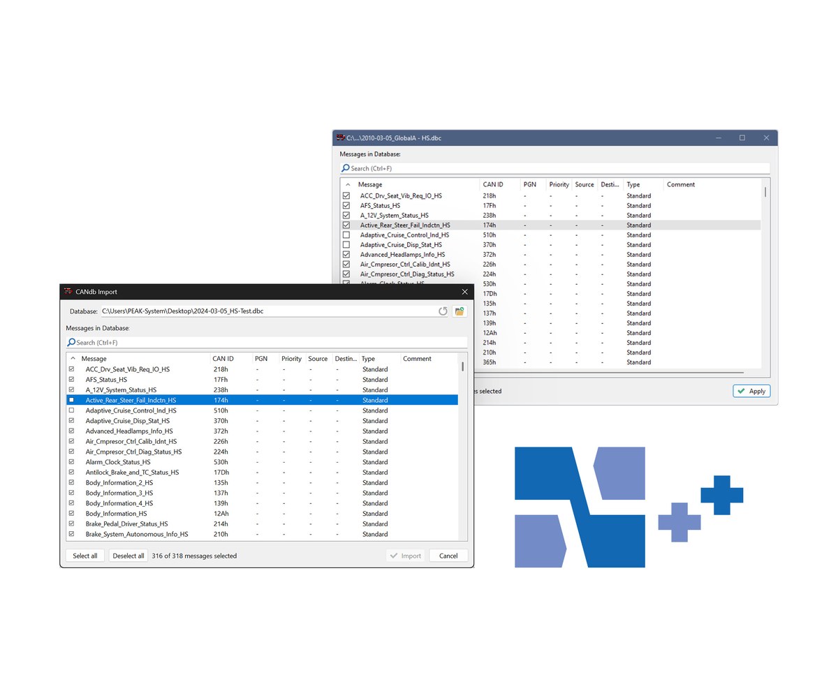

MICSIG TO GEN 4 Tablet Oscilloscope

The MICSIG TO is a GEN 4 portable tablet oscilloscope at 200 MHz or 300 MHz, with 2 or 4 channels, up to 2 GSa/s and 220 Mpts, a 10.1-inch touch screen, standard serial decoding (UART, CAN, CAN FD, LIN, SPI, I2C) and a built-in 7500 mAh battery, in 1.9 kg. Pertech, the exclusive MICSIG distributor in Israel, quotes in ILS with local invoicing, handles warranty in Israel and arranges calibration and repair.

TO highlights

  • Up to 300MHz bandwidth and 2GSa/s sampling, 2 or 4 channels
  • Up to 220Mpts memory with segmented storage (max 10,000 waveform events)
  • Waveform capture rate up to 300,000 wfms/s
  • Serial bus decoding: RS-232/422/485/UART, CAN, CAN FD, LIN, SPI, I2C, with CSV export
  • Built-in 7500mAh lithium battery, power lock for transport, 1.9kg
  • 10.1-inch capacitive touch display, 1280 x 800
  • Hardware digital filtering, low-pass and high-pass down to 30Hz
  • 32GB built-in storage for screenshots, video and waveform data
  • Remote control via SCPI, mobile apps (Android, iOS) and PC software

Models

ModelBandwidthChannelsSamplingMemory
TO3004300MHz42GSa/s220Mpts
TO2004200MHz42GSa/s220Mpts
TO2002200MHz21GSa/s110Mpts

Where the TO fits

  • Lab and on-site troubleshooting

Key Specifications

SpecValue
Bandwidth200MHz / 300MHz
Rise time<=1.75ns / <=1.16ns
Real-time sampling rate1GSa/s (TO2002) / 2GSa/s
Memory depth110Mpts (TO2002) / 220Mpts
Max. waveform capture rate78,000 / 300,000 wfms/s
Input sensitivity1mV/div – 10V/div (1MΩ); 1mV/div – 1V/div (50Ω)
Trigger typesEdge, Pulse Width, Logic, Nth Edge, Runt, Slope, Time Out, Video
InterfacesWi-Fi, USB 3.0/2.0 Host, USB Type-C, Grounding, HDMI, Trigger out
Battery7.4V, 7500mAh Li-Ion
Dimension / weight265 x 192 x 50mm / 1.9kg with battery

MICSIG TO in Israel

Buy the TO from Pertech, the exclusive MICSIG distributor in Israel: quotes in ILS and local invoicing, warranty handled in Israel, calibration and repair arranged through Pertech, some models in stock in Israel, and technical support from Pertech engineers.

Frequently asked questions

What is the MICSIG TO?

The MICSIG TO is a GEN 4 portable tablet oscilloscope at 200 MHz or 300 MHz, with 2 or 4 channels, up to 2 GSa/s and 220 Mpts, a 10.1-inch touch screen, standard serial decoding (UART, CAN, CAN FD, LIN, SPI, I2C) and a built-in 7500 mAh battery, in 1.9 kg.

Where can I buy the MICSIG TO in Israel?

From Pertech, the exclusive MICSIG distributor in Israel. Contact Pertech for a quote in ILS, availability and help choosing the model.

Who handles warranty and calibration in Israel?

Pertech handles MICSIG warranty in Israel: you return the unit to Pertech and Pertech deals with MICSIG. Pertech also arranges calibration and repair.

Does the TO work with the SigOFIT optical isolated probe?

MICSIG states that its oscilloscopes support all MICSIG probes, including the SigOFIT optical-fiber isolated probe, high-voltage differential probes and current probes. The SigOFIT has a standard BNC output, so it also works with other oscilloscope brands.

Can Pertech help me set it up?

Yes. Pertech engineers help with setup and application questions for MICSIG instruments bought through Pertech.

Related MICSIG products at Pertech

Need a quote for the MICSIG TO? Contact Pertech.
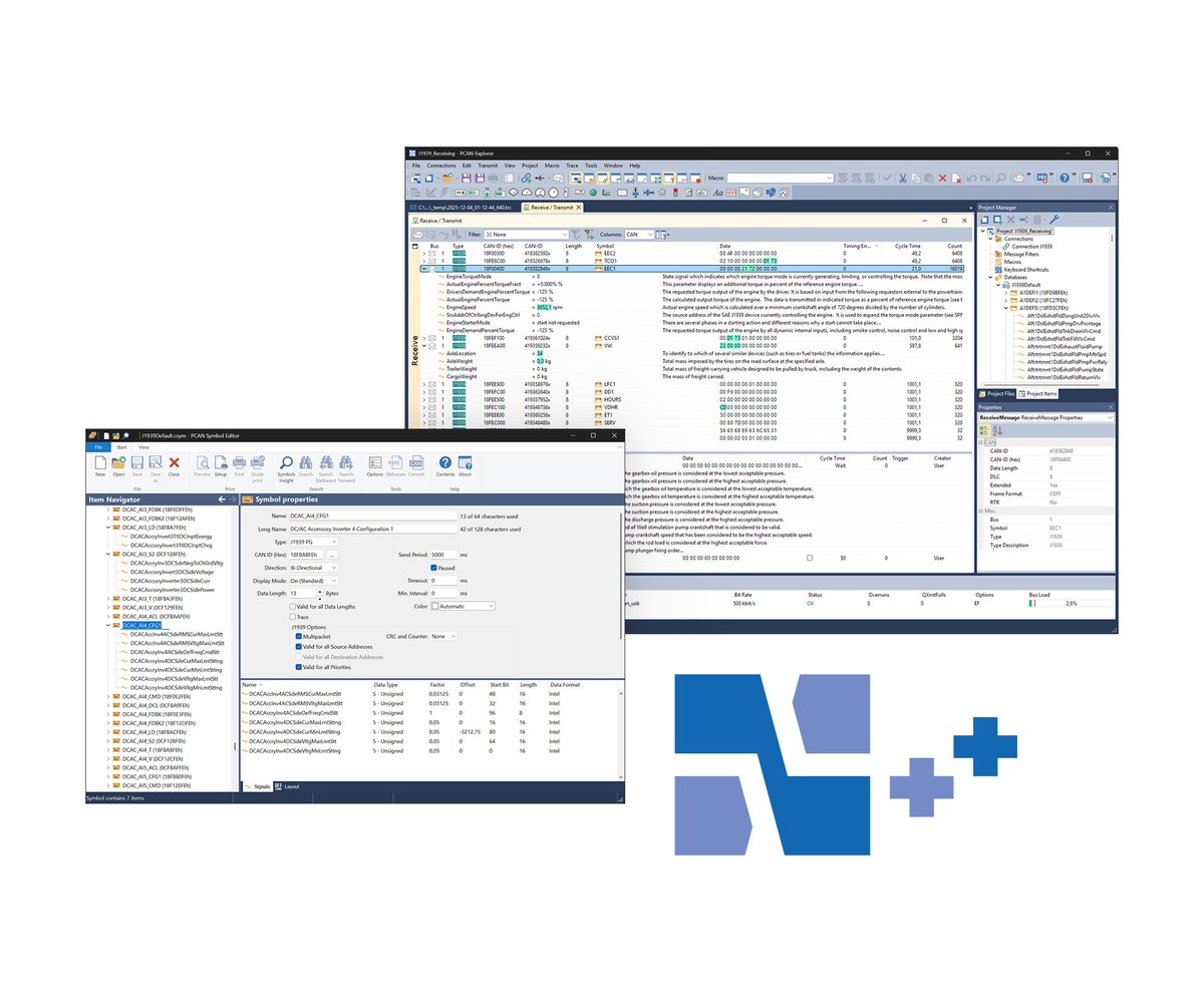

MICSIG ETO GEN 5 Tablet Oscilloscope

The MICSIG ETO is a GEN 5 tablet oscilloscope at 350 MHz or 500 MHz with 4 analog channels, 3 GSa/s, 360 Mpts memory, a 14-inch 1920 x 1200 touch screen and a built-in 13,500 mAh battery for the bench or the field. Pertech, the exclusive MICSIG distributor in Israel, quotes in ILS with local invoicing, handles warranty in Israel and arranges calibration and repair.

ETO highlights

  • Up to 500MHz bandwidth, 3GSa/s real-time sampling, 4 analog channels
  • Up to 360Mpts memory depth
  • Noise floor less than 90μVrms at 500MHz full bandwidth
  • 14-inch integrated touch screen, 1920 x 1200 resolution
  • Built-in 13,500mAh battery for desktop or field use, power-off lock for transport
  • Max. waveform capture rate 230,000wfms/s
  • Hardware digital filter down to 30Hz
  • Standard 75mm x 75mm VESA mount interface
  • SigTestUI multitasking system; soft rubber protected slim body

Models

ModelBandwidthRise timeChannels
ETO5004500MHz<=0.7ns4
ETO3504350MHz<=1ns4

Where the ETO fits

  • Desktop use
  • Field test

Key Specifications

SpecValue
Bandwidth350MHz / 500MHz
Rise time<=1ns / <=0.7ns
Analog channels4
Real-time sampling rate3GSa/s
Memory depth360Mpts
Max. waveform capture rate230,000wfms/s
Vertical resolution8bit
Noise<90μVrms
InterfacesUSB 3.0/2.0 Host, USB Type-C, HDMI, Trigger out
Display14-inch full touch, 1920 x 1200
Battery7.4V / 13500mAh Li-Ion
Dimension353 x 245 x 56mm

MICSIG ETO in Israel

Buy the ETO from Pertech, the exclusive MICSIG distributor in Israel: quotes in ILS and local invoicing, warranty handled in Israel, calibration and repair arranged through Pertech, some models in stock in Israel, and technical support from Pertech engineers.

Frequently asked questions

What is the MICSIG ETO?

The MICSIG ETO is a GEN 5 tablet oscilloscope at 350 MHz or 500 MHz with 4 analog channels, 3 GSa/s, 360 Mpts memory, a 14-inch 1920 x 1200 touch screen and a built-in 13,500 mAh battery for the bench or the field.

Where can I buy the MICSIG ETO in Israel?

From Pertech, the exclusive MICSIG distributor in Israel. Contact Pertech for a quote in ILS, availability and help choosing the model.

Who handles warranty and calibration in Israel?

Pertech handles MICSIG warranty in Israel: you return the unit to Pertech and Pertech deals with MICSIG. Pertech also arranges calibration and repair.

Does the ETO work with the SigOFIT optical isolated probe?

MICSIG states that its oscilloscopes support all MICSIG probes, including the SigOFIT optical-fiber isolated probe, high-voltage differential probes and current probes. The SigOFIT has a standard BNC output, so it also works with other oscilloscope brands.

Can Pertech help me set it up?

Yes. Pertech engineers help with setup and application questions for MICSIG instruments bought through Pertech.

Related MICSIG products at Pertech

Need a quote for the MICSIG ETO? Contact Pertech.
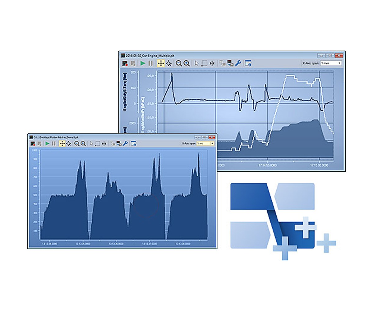

MICSIG MDO GEN 5 14-Inch Digital Storage Oscilloscope

The MICSIG MDO is MICSIG’s fifth-generation digital storage oscilloscope: up to 500 MHz, 4 analog channels, 3 GSa/s, 360 Mpts memory and a 14-inch 1920 x 1200 touch screen in a body only 3.58 cm thick, with wall and arm mounting. Its Mic-OPI probe interface works with all MICSIG probes, including the SigOFIT optical-fiber isolated probe. Pertech, the exclusive MICSIG distributor in Israel, quotes in ILS with local invoicing, handles warranty in Israel and arranges calibration and repair.

MDO highlights

  • Up to 500MHz bandwidth, 3GSa/s real-time sampling on 4 analog channels
  • 360Mpts memory depth with segmented storage acquisition
  • Noise less than 90μVrms at 500MHz full bandwidth
  • 14-inch integrated touch screen, 1920 x 1200 resolution
  • 3.58cm ultra-thin body, supports wall / arm mounting
  • Max. waveform capture rate 230,000wfms/s
  • Hardware digital filter to pass or block specific frequency ranges
  • Mic-OPI probe interface auto-identifies passive probe attenuation, one-click auto-calibration
  • Supports all Micsig probes: optical-fiber isolated, high-voltage differential, AC/DC current

Models

ModelBandwidthRise timeChannels
MDO5004500MHz<=0.7ns4
MDO3504350MHz<=1ns4
MDO2504250MHz<=1.4ns4

Key Specifications

SpecValue
Bandwidth250MHz / 350MHz / 500MHz
Rise time<=1.4ns / <=1ns / <=0.7ns
Analog channels4
Real-time sampling rate3GSa/s
Memory depth360Mpts
Max. waveform capture rate230,000wfms/s
Vertical resolution8bit
Noise<90μVrms
InterfacesUSB 3.0 Host, USB Type-C, HDMI, Trigger out (features text also lists LAN)
Display14-inch full touch, 1920 x 1200
Dimension400 x 280 x 35.8mm
SoftwareSigTestUI operating system; SCPI programming guide available

MICSIG MDO in Israel

Buy the MDO from Pertech, the exclusive MICSIG distributor in Israel: quotes in ILS and local invoicing, warranty handled in Israel, calibration and repair arranged through Pertech, some models in stock in Israel, and technical support from Pertech engineers.

Frequently asked questions

What is the MICSIG MDO?

The MICSIG MDO is MICSIG’s fifth-generation digital storage oscilloscope: up to 500 MHz, 4 analog channels, 3 GSa/s, 360 Mpts memory and a 14-inch 1920 x 1200 touch screen in a body only 3.58 cm thick, with wall and arm mounting. Its Mic-OPI probe interface works with all MICSIG probes, including the SigOFIT optical-fiber isolated probe.

Where can I buy the MICSIG MDO in Israel?

From Pertech, the exclusive MICSIG distributor in Israel. Contact Pertech for a quote in ILS, availability and help choosing the model.

Who handles warranty and calibration in Israel?

Pertech handles MICSIG warranty in Israel: you return the unit to Pertech and Pertech deals with MICSIG. Pertech also arranges calibration and repair.

Does the MDO work with the SigOFIT optical isolated probe?

MICSIG states that its oscilloscopes support all MICSIG probes, including the SigOFIT optical-fiber isolated probe, high-voltage differential probes and current probes. The SigOFIT has a standard BNC output, so it also works with other oscilloscope brands.

Can Pertech help me set it up?

Yes. Pertech engineers help with setup and application questions for MICSIG instruments bought through Pertech.

Related MICSIG products at Pertech

Need a quote for the MICSIG MDO? Contact Pertech.
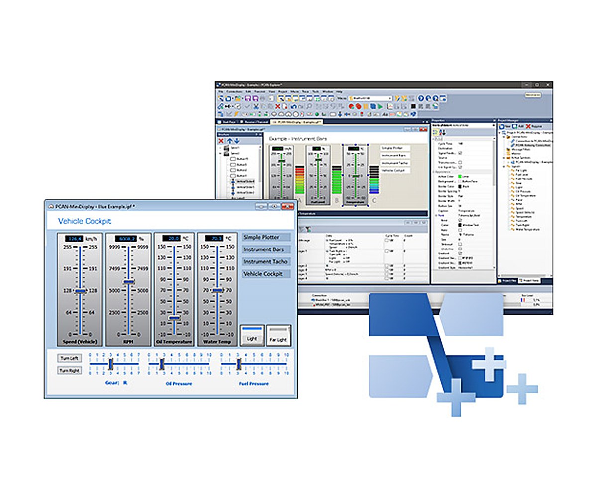

MICSIG SigOFIT Gen 2 Optical-Fiber Isolated Probe (MOIP)

The MICSIG SigOFIT Gen 2 (MOIP series) is an optical-fiber isolated probe from 200 MHz to 1 GHz with an 85 kVpk common-mode voltage range, CMRR of 180 dB at DC and 108 dB at 1 GHz, 1% DC gain accuracy and noise of 0.45 mVrms. Laser power and signal over fiber mean no batteries in the probe head and uninterrupted testing. Pertech, the exclusive MICSIG distributor in Israel, quotes in ILS with local invoicing, handles warranty in Israel and arranges calibration and repair.

SigOFIT Gen 2 highlights

  • Bandwidth 200MHz to 1GHz, rise time down to <=450ps
  • Common mode voltage range 85kVpk
  • CMRR 180dB at DC, up to 128dB at 100MHz, 108dB at 1GHz
  • DC gain accuracy 1%, noise <=0.45mVrms
  • Differential ranges up to +/-6250 V with attenuator tips (by model)
  • Laser power and signal over fiber, no batteries, 24 x 365 uninterrupted testing
  • Input capacitance as low as 1pF, short coaxial leads for GaN testing
  • AutoZero in less than 1 second, ready immediately after power-on
  • Standard BNC interface, compatible with all oscilloscope brands

Models

ModelBandwidthRise timeCmrr at bw
MOIP200P200MHz<=1.75ns122dB @ 200MHz
MOIP350P350MHz<=1ns118dB @ 350MHz
MOIP500P500MHz<=700ps114dB @ 500MHz
MOIP1000P1GHz<=450ps108dB @ 1GHz

Where the SigOFIT Gen 2 fits

  • Motor drive, power converter and electronic ballast design
  • GaN, SiC, IGBT half/full bridge design
  • Inverter, UPS and switching power supply design
  • High voltage, high bandwidth safety test
  • Power device evaluation
  • Current shunt measurements
  • EMI and ESD troubleshooting
  • Floating measurements

Key Specifications

SpecValue
Bandwidth200MHz / 350MHz / 500MHz / 1GHz
Rise time<=1.75ns / <=1ns / <=700ps / <=450ps
CMRRDC: 180dB; 122dB @ 200MHz to 108dB @ 1GHz
Differential voltage rangeUp to +/-6250 V, by model and attenuator tip
Noise0.45mVrms
DC gain accuracy1%
Common mode voltage range85kVpk
Input capacitanceAs low as 1pF
InterfaceUniversal BNC

Standard and optional tips: MOIP200P: OP20 (+/-25V) standard, OP50/OP200/OP1000/OP2000/OP5000 optional. MOIP350P: OP20 (+/-25V) and OP1000 (+/-1250V) standard, others optional. Third tip column: OP50 (+/-25V) and OP5000 (+/-2500V) standard; OP20, OP100, OP2000, OP10000 optional.

MICSIG SigOFIT Gen 2 in Israel

Buy the SigOFIT Gen 2 from Pertech, the exclusive MICSIG distributor in Israel: quotes in ILS and local invoicing, warranty handled in Israel, calibration and repair arranged through Pertech, some models in stock in Israel, and technical support from Pertech engineers.

Frequently asked questions

What is the MICSIG SigOFIT Gen 2?

The MICSIG SigOFIT Gen 2 (MOIP series) is an optical-fiber isolated probe from 200 MHz to 1 GHz with an 85 kVpk common-mode voltage range, CMRR of 180 dB at DC and 108 dB at 1 GHz, 1% DC gain accuracy and noise of 0.45 mVrms. Laser power and signal over fiber mean no batteries in the probe head and uninterrupted testing.

Where can I buy the MICSIG SigOFIT Gen 2 in Israel?

From Pertech, the exclusive MICSIG distributor in Israel. Contact Pertech for a quote in ILS, availability and help choosing the model.

Who handles warranty and calibration in Israel?

Pertech handles MICSIG warranty in Israel: you return the unit to Pertech and Pertech deals with MICSIG. Pertech also arranges calibration and repair.

Does the SigOFIT Gen 2 work with any oscilloscope?

MICSIG specifies a standard BNC output for the SigOFIT Gen 2, compatible with oscilloscopes from other brands as well as MICSIG’s own.

Can Pertech help me set it up?

Yes. Pertech engineers help with setup and application questions for MICSIG instruments bought through Pertech.

Related MICSIG products at Pertech

Need a quote for the MICSIG SigOFIT Gen 2? Contact Pertech.
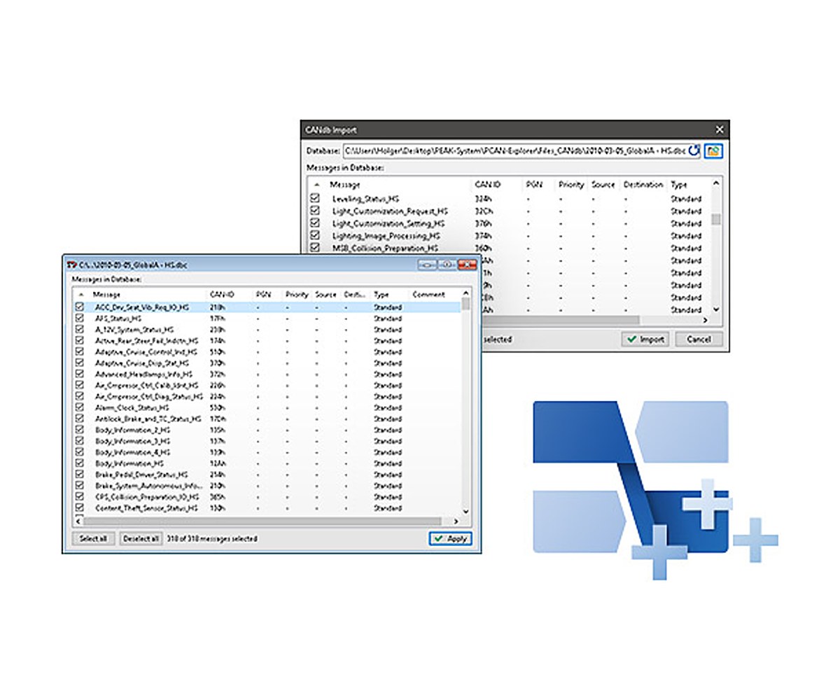

Siglent SSU5000A Mechanical RF Switch

The Siglent SSU5000A is a compact USB-controlled mechanical RF switch with 1 to 4 SPDT or 1 to 2 SP6T switches, from DC to 18 GHz, 26.5 GHz or 50 GHz, with SMA or 2.4 mm connectors. Pertech, an authorized Siglent distributor in Israel, quotes in ILS with local invoicing, handles warranty in Israel and arranges calibration and repair.

SSU5000A highlights

  • Frequency range up to 18 GHz, 26.5 GHz or 50 GHz
  • 1 to 4 independent SPDT switches, or 1 to 2 SP6T switches
  • SMA female (18 and 26.5 GHz) or 2.4 mm female (50 GHz) connectors
  • Low insertion loss and good impedance matching
  • Short switching time
  • SCPI control via VISA and EasySSU software
  • USB connectivity
  • Compact size: 153 x 62.4 x 137.5 mm (W x H x D)

Models

ModelFrequencySwitchesConnector
SSU5181ADC-18 GHz1 x SPDTSMA female
SSU5182ADC-18 GHz2 x SPDTSMA female
SSU5183ADC-18 GHz3 x SPDTSMA female
SSU5184ADC-18 GHz4 x SPDTSMA female
SSU5261ADC-26.5 GHz1 x SPDTSMA female
SSU5262ADC-26.5 GHz2 x SPDTSMA female
SSU5263ADC-26.5 GHz3 x SPDTSMA female
SSU5264ADC-26.5 GHz4 x SPDTSMA female
SSU5265ADC-26.5 GHz1 x SP6TSMA female
SSU5266ADC-26.5 GHz2 x SP6TSMA female
SSU5501ADC-50 GHz1 x SPDT2.4 mm female
SSU5502ADC-50 GHz2 x SPDT2.4 mm female
SSU5503ADC-50 GHz3 x SPDT2.4 mm female
SSU5504ADC-50 GHz4 x SPDT2.4 mm female

Where the SSU5000A fits

  • Multi-port testing of microwave and millimeter-wave systems

Key Specifications

SpecValue
Frequency rangeDC-18 GHz, DC-26.5 GHz or DC-50 GHz (by model)
Switch typesSPDT (1 common to 1 of 2) or SP6T (1 common to 1 of 6)
Number of switches1-4 SPDT or 1-2 SP6T
RF connectorSMA female or 2.4 mm female
ControlSCPI via VISA, EasySSU software
InterfaceUSB
Size (W x H x D)153 x 62.4 x 137.5 mm
Models14

Siglent SSU5000A in Israel

Buy the SSU5000A from Pertech, an authorized Siglent distributor in Israel: quotes in ILS and local invoicing, warranty handled in Israel, calibration and repair arranged through Pertech, some models in stock in Israel, and technical support from Pertech engineers.

Frequently asked questions

What is the Siglent SSU5000A?

The Siglent SSU5000A is a compact USB-controlled mechanical RF switch with 1 to 4 SPDT or 1 to 2 SP6T switches, from DC to 18 GHz, 26.5 GHz or 50 GHz, with SMA or 2.4 mm connectors.

Which SSU5000A models are there?

SSU5181A (frequency DC-18 GHz, switches 1 x SPDT, connector SMA female); SSU5182A (frequency DC-18 GHz, switches 2 x SPDT, connector SMA female); SSU5183A (frequency DC-18 GHz, switches 3 x SPDT, connector SMA female); SSU5184A (frequency DC-18 GHz, switches 4 x SPDT, connector SMA female); SSU5261A (frequency DC-26.5 GHz, switches 1 x SPDT, connector SMA female); SSU5262A (frequency DC-26.5 GHz, switches 2 x SPDT, connector SMA female); SSU5263A (frequency DC-26.5 GHz, switches 3 x SPDT, connector SMA female); SSU5264A (frequency DC-26.5 GHz, switches 4 x SPDT, connector SMA female); SSU5265A (frequency DC-26.5 GHz, switches 1 x SP6T, connector SMA female); SSU5266A (frequency DC-26.5 GHz, switches 2 x SP6T, connector SMA female); SSU5501A (frequency DC-50 GHz, switches 1 x SPDT, connector 2.4 mm female); SSU5502A (frequency DC-50 GHz, switches 2 x SPDT, connector 2.4 mm female); SSU5503A (frequency DC-50 GHz, switches 3 x SPDT, connector 2.4 mm female); SSU5504A (frequency DC-50 GHz, switches 4 x SPDT, connector 2.4 mm female).

Where can I buy the Siglent SSU5000A in Israel?

From Pertech, an authorized Siglent distributor in Israel. Contact Pertech for a quote in ILS, availability and help choosing the model and options.

Who handles warranty and calibration in Israel?

Pertech handles Siglent warranty in Israel: you return the unit to Pertech and Pertech deals with Siglent. Pertech also arranges calibration and repair.

Can Pertech help me set it up?

Yes. Pertech engineers help with setup and application questions for Siglent instruments bought through Pertech.
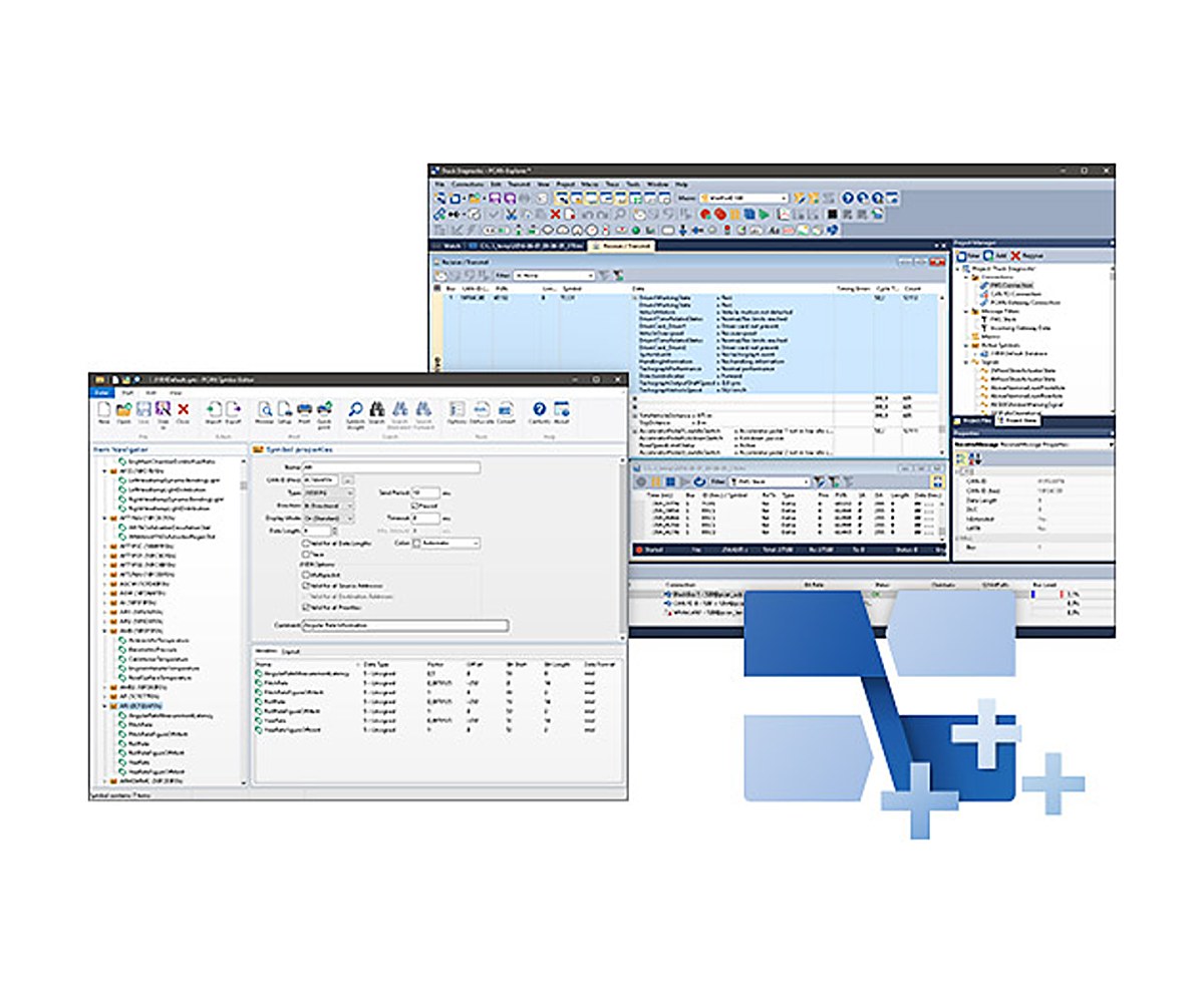
Related Siglent products at Pertech

Need a quote for the Siglent SSU5000A? Contact Pertech.
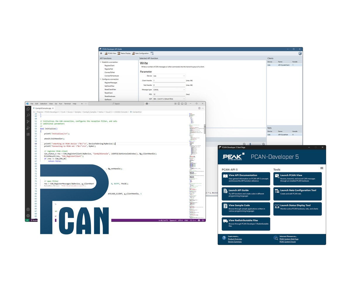

Siglent SSM5000A RF Switch Matrix

The Siglent SSM5000A is an RF switch matrix that extends the ports of a network analyzer, signal generator or spectrum analyzer: up to 4 inputs and 24 outputs, from 9 kHz to 9 GHz or 100 kHz to 26.5 GHz, in a 19-inch chassis. Pertech, an authorized Siglent distributor in Israel, quotes in ILS with local invoicing, handles warranty in Israel and arranges calibration and repair.

SSM5000A highlights

  • Frequency up to 9 GHz or 26.5 GHz
  • Up to 4 input ports and 24 output ports
  • Network analyzer port extension, e.g. 24 single ports, 12 full 2-ports, 6 full 4-ports or 1 full 24-port
  • Extends a signal source and spectrum analyzer to 24 ports for multi-DUT TX/RX testing
  • Simplified multi-port calibration algorithm
  • Direct Control in/out interface for further port expansion
  • Works with Siglent and other mainstream instruments
  • 3.5 mm female RF connectors, 50 ohm
  • Fits 19-inch standard chassis

Models

ModelFrequencyInputsOutputs
SSM5122A9 kHz-9 GHz212
SSM5124A9 kHz-9 GHz224
SSM5142A9 kHz-9 GHz412
SSM5144A9 kHz-9 GHz424
SSM5321A100 kHz-26.5 GHz26
SSM5342A100 kHz-26.5 GHz412

Where the SSM5000A fits

  • Multi-port S-parameter testing with a network analyzer
  • Multi-DUT transmit and receive testing with a signal source and spectrum analyzer
  • Antenna testing
  • 5G component and module testing

Key Specifications

SpecValue
Frequency range9 kHz-9 GHz or 100 kHz-26.5 GHz (by model)
Input ports2 or 4
Output ports6, 12 or 24
Max input power20 dBm
Max input DC voltage35 V
Characteristic impedance50 ohm
RF connector3.5 mm female
Screen2.4-inch

Siglent SSM5000A in Israel

Buy the SSM5000A from Pertech, an authorized Siglent distributor in Israel: quotes in ILS and local invoicing, warranty handled in Israel, calibration and repair arranged through Pertech, some models in stock in Israel, and technical support from Pertech engineers.

Frequently asked questions

What is the Siglent SSM5000A?

The Siglent SSM5000A is an RF switch matrix that extends the ports of a network analyzer, signal generator or spectrum analyzer: up to 4 inputs and 24 outputs, from 9 kHz to 9 GHz or 100 kHz to 26.5 GHz, in a 19-inch chassis.

Which SSM5000A models are there?

SSM5122A (frequency 9 kHz-9 GHz, inputs 2, outputs 12); SSM5124A (frequency 9 kHz-9 GHz, inputs 2, outputs 24); SSM5142A (frequency 9 kHz-9 GHz, inputs 4, outputs 12); SSM5144A (frequency 9 kHz-9 GHz, inputs 4, outputs 24); SSM5321A (frequency 100 kHz-26.5 GHz, inputs 2, outputs 6); SSM5342A (frequency 100 kHz-26.5 GHz, inputs 4, outputs 12).

Where can I buy the Siglent SSM5000A in Israel?

From Pertech, an authorized Siglent distributor in Israel. Contact Pertech for a quote in ILS, availability and help choosing the model and options.

Who handles warranty and calibration in Israel?

Pertech handles Siglent warranty in Israel: you return the unit to Pertech and Pertech deals with Siglent. Pertech also arranges calibration and repair.

Can Pertech help me set it up?

Yes. Pertech engineers help with setup and application questions for Siglent instruments bought through Pertech.
Related Siglent products at Pertech

Need a quote for the Siglent SSM5000A? Contact Pertech.

Siglent SDM4065A 6½-Digit Digital Multimeter

The Siglent SDM4065A is a 6½-digit (2,200,000 count) dual-display bench multimeter with 0.0035% one-year DC voltage accuracy and up to 50,000 readings per second. The SDM4065A-SC version adds a built-in scanner with 12 multi-purpose and 4 current channels, including RTD and thermocouple temperature. Pertech, an authorized Siglent distributor in Israel, quotes in ILS with local invoicing, handles warranty in Israel and arranges calibration and repair.

SDM4065A highlights

  • Real 6.5-digit resolution (2,200,000 counts) with dual display
  • Up to 50k readings/s
  • 0.0035% one-year DC voltage accuracy
  • DC current from 200 uA to 10 A range
  • 512 MB RAM caching up to 2M readings; 256 MB NAND flash for readings, images and configs
  • 4 display modes: numerical, bar meter, trend chart, histogram
  • -SC model scanner: 12 multi-purpose + 4 current channels, including RTD and thermocouple temperature
  • 5-inch true-color TFT-LCD
  • EasyDMM-X PC control and sampling software; SCPI

Models

ModelDigitsScanner
SDM4065A6.5No
SDM4065A-SC6.5Yes (12 multi-purpose + 4 current channels)

Where the SDM4065A fits

  • High-accuracy, high-precision measurement
  • R&D burn-in testing (scanner model)
  • Production testing (scanner model)

Key Specifications

SpecValue
Resolution6.5 digits (2,200,000 counts)
DC voltage accuracy (1 year)0.0035%
DC voltage range200 mV to 1000 V
AC voltage range200 mV to 750 V
DC current range200 uA to 10 A
Reading rateUp to 50k readings/s
Memory512 MB RAM (up to 2M readings), 256 MB NAND flash
Scanner (-SC only)12 multi-purpose + 4 current channels
Scanner functionsDCV, ACV, DCI, ACI, 2WR, 4WR, CAP, FREQ, DIODE, CONT, TEMP (RTD and thermocouple)
Display5-inch true-color TFT-LCD

Siglent SDM4065A in Israel

Buy the SDM4065A from Pertech, an authorized Siglent distributor in Israel: quotes in ILS and local invoicing, warranty handled in Israel, calibration and repair arranged through Pertech, some models in stock in Israel, and technical support from Pertech engineers.

Frequently asked questions

What is the Siglent SDM4065A?

The Siglent SDM4065A is a 6½-digit (2,200,000 count) dual-display bench multimeter with 0.0035% one-year DC voltage accuracy and up to 50,000 readings per second. The SDM4065A-SC version adds a built-in scanner with 12 multi-purpose and 4 current channels, including RTD and thermocouple temperature.

Which SDM4065A models are there?

SDM4065A (digits 6.5, scanner No); SDM4065A-SC (digits 6.5, scanner Yes (12 multi-purpose + 4 current channels)).

Where can I buy the Siglent SDM4065A in Israel?

From Pertech, an authorized Siglent distributor in Israel. Contact Pertech for a quote in ILS, availability and help choosing the model and options.

Who handles warranty and calibration in Israel?

Pertech handles Siglent warranty in Israel: you return the unit to Pertech and Pertech deals with Siglent. Pertech also arranges calibration and repair.

Can Pertech help me set it up?

Yes. Pertech engineers help with setup and application questions for Siglent instruments bought through Pertech.
Related Siglent products at Pertech

Need a quote for the Siglent SDM4065A? Contact Pertech.
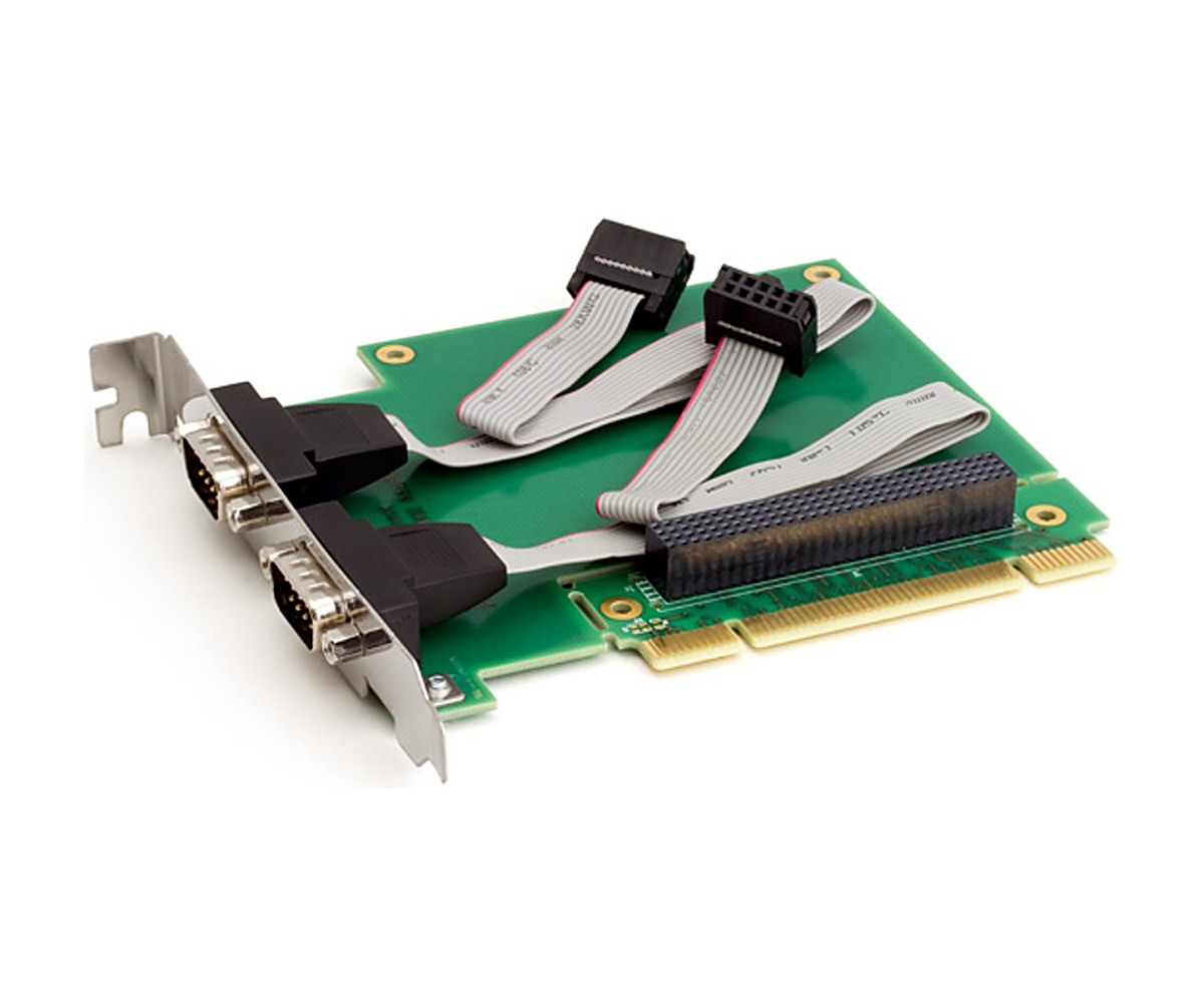

Siglent SDM4055A 5½-Digit Digital Multimeter

The Siglent SDM4055A is a 5½-digit (220,000 count) dual-display bench multimeter with 0.015% one-year DC voltage accuracy and 5 to 4,800 readings per second. The SDM4055A-SC version adds a built-in scanner with 12 multi-purpose and 4 current channels, including RTD and thermocouple temperature. Pertech, an authorized Siglent distributor in Israel, quotes in ILS with local invoicing, handles warranty in Israel and arranges calibration and repair.

SDM4055A highlights

  • Real 5.5-digit resolution (220,000 counts) with dual display
  • Reading rate from 5 to 4.8k readings/s
  • 0.015% one-year DC voltage accuracy
  • True-RMS AC voltage and AC current
  • Automatic switching between 10 A and 3 A current modes; up to 30 A with an external shunt
  • 512 MB RAM caching up to 2M readings; 256 MB NAND flash for readings, images and configs
  • -SC model scanner: 12 multi-purpose + 4 current channels, including RTD and thermocouple temperature
  • 5-inch true-color TFT-LCD; numerical, trend chart, bar meter and histogram views
  • EasyDMM-X PC control and sampling software; SCPI

Models

ModelDigitsScanner
SDM4055A5.5No
SDM4055A-SC5.5Yes (12 multi-purpose + 4 current channels)

Where the SDM4055A fits

  • High-precision, multifunction and automated measurement
  • R&D burn-in testing (scanner model)
  • Production testing (scanner model)

Key Specifications

SpecValue
Resolution5.5 digits (220,000 counts)
DC voltage accuracy (1 year)0.015%
DC voltage range200 mV to 1000 V
AC voltage range200 mV to 750 V
DC current range20 mA to 10 A
Reading rate5 to 4.8k readings/s
Memory512 MB RAM (up to 2M readings), 256 MB NAND flash
Scanner (-SC only)12 multi-purpose + 4 current channels
Scanner functionsDCV, ACV, DCI, ACI, 2WR, 4WR, CAP, FREQ, DIODE, CONT, TEMP (RTD and thermocouple)
Display5-inch true-color TFT-LCD

Siglent SDM4055A in Israel

Buy the SDM4055A from Pertech, an authorized Siglent distributor in Israel: quotes in ILS and local invoicing, warranty handled in Israel, calibration and repair arranged through Pertech, some models in stock in Israel, and technical support from Pertech engineers.

Frequently asked questions

What is the Siglent SDM4055A?

The Siglent SDM4055A is a 5½-digit (220,000 count) dual-display bench multimeter with 0.015% one-year DC voltage accuracy and 5 to 4,800 readings per second. The SDM4055A-SC version adds a built-in scanner with 12 multi-purpose and 4 current channels, including RTD and thermocouple temperature.

Which SDM4055A models are there?

SDM4055A (digits 5.5, scanner No); SDM4055A-SC (digits 5.5, scanner Yes (12 multi-purpose + 4 current channels)).

Where can I buy the Siglent SDM4055A in Israel?

From Pertech, an authorized Siglent distributor in Israel. Contact Pertech for a quote in ILS, availability and help choosing the model and options.

Who handles warranty and calibration in Israel?

Pertech handles Siglent warranty in Israel: you return the unit to Pertech and Pertech deals with Siglent. Pertech also arranges calibration and repair.

Can Pertech help me set it up?

Yes. Pertech engineers help with setup and application questions for Siglent instruments bought through Pertech.
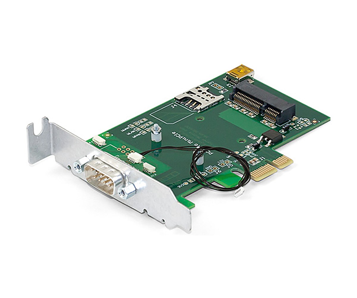
Related Siglent products at Pertech

Need a quote for the Siglent SDM4055A? Contact Pertech.
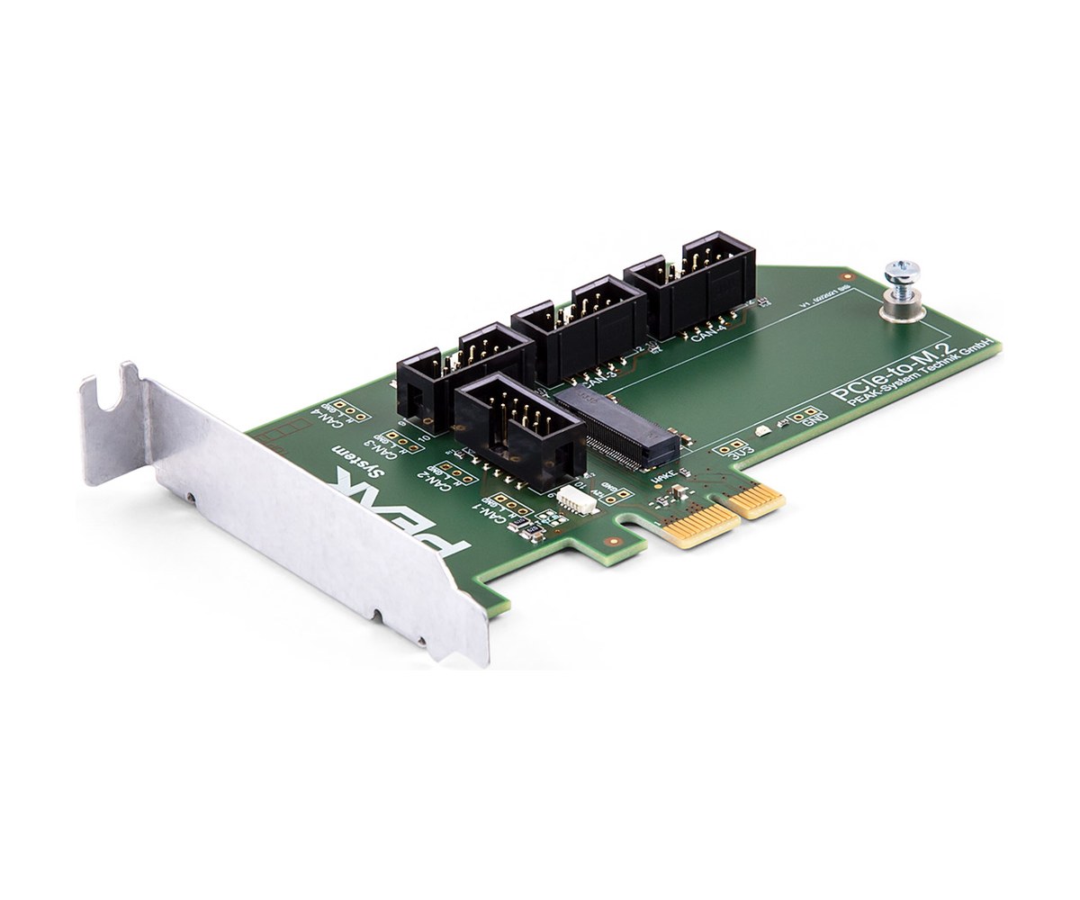

upbtn
Skip to content