


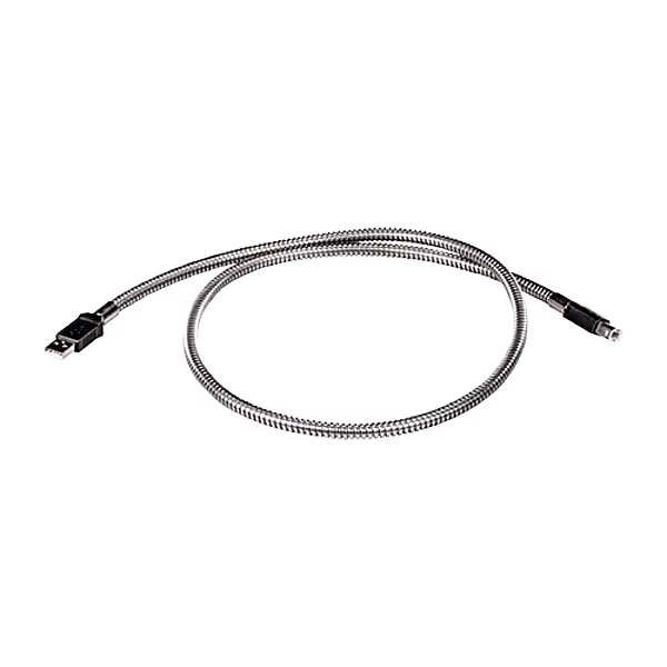
USB METAL ARMORED 1 MT
Item number CBLUSBM1
Rugged 1MT metal-jacketed USB tethering cable. Armored for durability, ensures reliable connection between Graphite expansion racks and host devices.

Item number CBLUSBM1
Rugged 1MT metal-jacketed USB tethering cable. Armored for durability, ensures reliable connection between Graphite expansion racks and host devices.
Item number CAT5E-XAM12-XAM12-18
The 18ft Gigabit CAT5e cable is designed for reliable high-speed data connections in industrial and outdoor applications. Featuring two space-saving 115-degree angled X-Code M12 connectors, it ensures secure and streamlined connections between M12 Ethernet devices.

Item number TMPCNS06
Standard Connectors are for use with the Standard Quick Disconnect TC Probes. They are available in both male and female termination, and include a “write on label” for easy identification. The female standard connector is a universal connector, meaning it can be used to terminate male versions of both the standard and miniature connector.
Item number LSAHC001
Aluminum construction and hinge clamp style. It works with ZFG, ZGG, ZFH, and ZGH models

Item number CBLGEN02
The CBL RS232 BARE WIRES is a 10-foot communication cable designed to connect Graphite®, DSP, G3, or Modular Controller series devices to RS-232 interfaces via unterminated (bare) wires. Provides flexibility for custom wiring configurations, allowing connection to a variety of devices with open RS-232 terminals. Ideal for specialized integration scenarios requiring direct wire connections.
Item number PAXCDS10
Dual relay version for PAX units only. When one relay is energized, it supports 5 amps at 120/240 VAC or 28 VDC (resistive load).

Item number PAXLBK30
These label kits provide a unique way to identify your display with one of 189 different engineering units. The label lights up from inside the PAX or PAX Lite Meters where it is protected from washdown and dirty environments
Item number CRA000AD07070000
The Model CRA000 AD070 70000 adapter plate provides the necessary hardware to install a CRx000 07 into an existing G307K2 cutout. This panel is made out of black Polycarbonate plastic that matches the material used on the CRx00007
Item number CAT5E-RM12-RJ45-20
The CAT5E-RM12-RJ45-20 Shielded 20′ Cable is a durable, high performing 20-foot twisted pair cable with 90° M12 to RJ45 connector. Meets and exceeds Cat5E specifications. Perfect for high temperature settings with cable rated for 75° C. Ideal for 10Base-T(IEEE 802.3), 100Base-TX(IEEE 802.3u), 1000Base-TX connections.

Item number 2ZR6AC-6
The durable 2ZR6AC-6 – 6′ Multimode Duplex Fiber Optic Cable with ST-LC help add fiber capability to industrial applications. 6 feet in length, diameter of 62.5/125, wavelength of 1310nm, and maximum insertion loss of 0.4dB. Safety rated and high performing in harsh conditions from -20 to 70 °C.

Item number PWR-RM12-A-15
The 15’ PWR-RM12-A-15 Power Cable with IP67 Rating is designed for use with N-TRON® M12 products. This IP67 rated, shielded, straight 15-foot power cable has a 90 degree M12 connector on one end and bare wire on the other. Suitable for indoor/outdoor use and direct burial, offering superior performance in harsh industrial and environmental conditions.

Item number PWR-RM12-A-2
The 2’ PWR-RM12-A-2 Power Cable with IP67 Rating is designed for use with N-TRON® M12 products. This IP67 rated, shielded, straight 2-foot power cable has a 90 degree M12 connector on one end and bare wire on the other. Suitable for indoor/outdoor use and direct burial, offering superior performance in harsh industrial and environmental conditions.
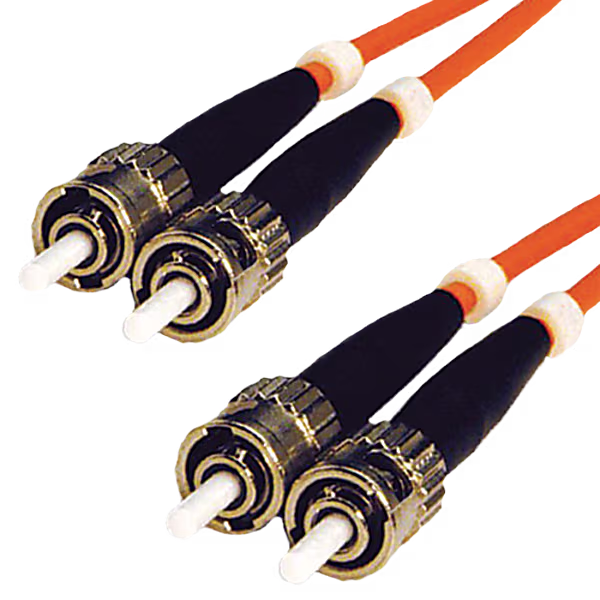
Item number 2ZR6AA-220
The durable 2ZR6AA-220- 220′ Multimode Duplex Fiber Optic Cable with ST-ST connectors help add fiber capability to industrial applications. 220 feet in length, diameter of 62.5/125, wavelength of 1310nm, and maximum insertion loss of 0.4dB. Safety rated and high performing in harsh conditions from -20 to 70 °C.
Item number URMK
This accessory is a universal rack mount kit used for mounting various equipment in a standard rack.

Item number CBLIDE03
The G3/MC TO IDEC MICRO SMART is a 10-foot communication cable specifically designed to connect Graphite®, DSP, G3, or Modular Controller series devices to the IDEC MicroSmart Series of programmable logic controllers. This reliable cable facilitates seamless data exchange and communication between these industrial automation components.
Item number CBLYAS02
The YASKAWA FSP DRIVE cable provides a 10-foot connection between Graphite®, Data Station Plus (DSP), G3, or Modular Controller units and Yaskawa FSP series drives. This cable enables seamless communication for drive control and data acquisition.

Item number CBLRLC02
The CBL RJ12-RJ12 10′ CROSSED is a ten-foot communication cable designed for direct connection between two Graphite®, DSP, G3, or Modular Controller series devices. Featuring RJ12 connectors on both ends with a crossed wiring configuration, this cable facilitates specific communication protocols between compatible Red Lion HMIs and controllers over a convenient ten-foot length.

Item number CCBRPG00
The 7P CONNECTOR is a key accessory designed for use with Rotary Pulse Generators. This connector ensures a reliable electrical interface, facilitating accurate signal transmission for position and speed feedback in various automation and control applications utilizing rotary encoders.

Item number CBLMDM00
The CBL MODEM 9PIN MALE is a 10-foot communication cable designed to connect Graphite®, DSP, G3, or Modular Controller series devices to a modem equipped with a standard DB9 male connector. Facilitates seamless data exchange and communication for remote access and data transfer applications.
Item number CBLMOD01
The CBL MODICON (RS232) is a 10-foot communication cable designed to connect Graphite®, DSP, G3, or Modular Controller series devices to Modicon programmable logic controllers or other devices utilizing the RS-232 communication protocol. Facilitates seamless serial data exchange between Red Lion HMIs/controllers and Modicon equipment.
Item number CBLSIE05
The G3/MC-SIE 545/555 RS232 is a 10-foot communication cable facilitating RS-232 connection between Graphite®, Data Station Plus (DSP), or G3 Modular Controller units and Siemens 545/555 PLCs.
Item number CT005001
The Model CT measures currents up to 50 amps with a 100 mA AC output.
\

Item number CBLUSBM1
Rugged 1MT metal-jacketed USB tethering cable. Armored for durability, ensures reliable connection between Graphite expansion racks and host devices.
Item number CUB5COM2
The CUB5 RS-232 Serial Communications Plug-In Option Card adds serial communication functionality to CUB5 units using the RS-232 standard. This half-duplex interface is ideal for point-to-point communication in applications requiring simple and direct data exchange.
Item number CAT5E-XAM12-RJ45-21
The 21ft Gigabit Shielded CAT5e cable is engineered for reliable high-speed data transfer in industrial and outdoor settings. It features a robust, space-efficient 115-degree angled X-Code M12 connector, ensuring secure connections to standard RJ45 ports.
Item number CAT5E-XM12-RJ45-8
The 8ft Gigabit Shielded CAT5e cable features a secure straight X-Code M12 connector for devices and an RJ45 connector for networking. Shielded against EMI/RFI for consistent gigabit speeds in demanding environments like automation. Durable build ensures dependable long-distance connectivity.
Item number CAT5E-XM12-XAM12-16
The 16ft shielded Gigabit CAT5e cable provides a robust, high-speed connection for industrial devices. Featuring a straight X-Code M12 connector and a space-saving 115-degree angled X-Code M12, it offers flexible routing in tight setups. Shielding ensures reliable gigabit data transfer between M12 ports by minimizing EMI/RFI. Ideal for short, secure links.
Item number CAT5E-XAM12-XAM12-14
The 14ft Gigabit CAT5e cable is designed for reliable high-speed data connections in industrial and outdoor applications. Featuring two space-saving 115-degree angled X-Code M12 connectors, it ensures secure and streamlined connections between M12 Ethernet devices.
Item number CBLTEL00
The G3 TELEMECHANIQUE RS485 is a 10-foot communication cable designed to connect Graphite®, Data Station Plus (DSP), or G3 Modular Controller units to a Telemecanique PLC functioning as a Unitelway Master via RS-485.

Item number GMFIBER-SFP-500
The GMFIBER-SFP-500 is a Gigabit multimode SFP transceiver employing LC connectors and operating at an 850nm wavelength. Facilitates high-speed data transfer over multimode fiber for distances up to 550 meters, enabling Gigabit Ethernet connectivity.

Item number FMFIBER-SFP-2K
The MISC 100Mbs MM FBR TR is a 100Base-FX small form-factor pluggable (SFP) transceiver. It utilizes LC connectors, supports multimode fiber, operates at a 1310nm wavelength, and has a transmission distance of up to 2 kilometers, providing a reliable fiber optic connection for 100Mbps Ethernet.

Item number RBC48005
The C48C is supplied with an output board installed. The output board is preconfigured for the type of output needed, based upon the Model ordered. All relay output boards are field replaceable. This output relay board is used with C48CB004, C48CB009, C48CB014, C48CB104, C48CB109, C48CB114 and C48CB119.
LTE FME connected antenna 250cm length
Item number E-022
LTE FME connected antenna 250cm length
4G/3G cellular antenna with 1m cable to be hole mounted for Ewon Cosy 131 APAC
Item number FAC90801_0000
Ewon antenna – 4G/3G JAPAN antenna with 1m cable to be hole mounted for Ewon Cosy 131

Item number CAT5E-XAM12-RJ45-328
The 328ft Gigabit Shielded CAT5e cable is engineered for reliable high-speed data transfer in industrial and outdoor settings. It features a robust, space-efficient 115-degree angled X-Code M12 connector, ensuring secure connections to standard RJ45 ports.
Connects CAN/CAN FD compontents (RJ45 to D-Sub 9)
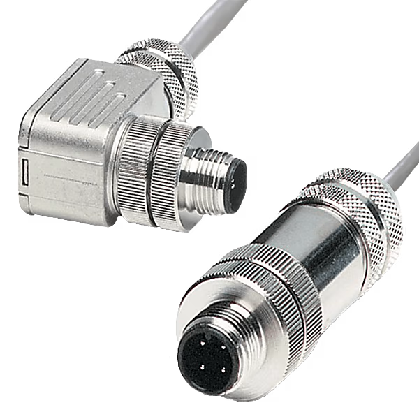
Item number 1.04.0074.01000
The Ixxat CAN adapter cable (0.2 m total length) efficiently converts a RJ45 socket to a D-Sub 9 plug and is tailored for usage with the Ixxat USB-to-CAN series. It is an essential accessory to support broad compatibility and secure data transfer in CAN networks.

Accessory for Ixxat FRC-EP190 and CANnector
Item number 1.04.0089.00201
The Ixxat DoubleCAN cable with D-Sub connectors is a practical accessory for FRC-EP190 and CANnector devices. It is used to easily separate two different CAN interfaces, with each connector offering distinct interface options based on the device variant. Its shielded design and twisted wires ensure reliable data transmission.

Item number 5400100
The TSBM-75 Block Mount is designed for secure retention of 3/4″ diameter sensors, including LMP, PSAC, and PSAH models. Durable construction ensures reliable sensor integration.

Item number PAXCDC20
Expand the communication capabilities of your PAX® panel meter with the RS-232 Serial Communication Plug-in Card. This card enables reliable, multi-point data exchange over long distances using a balanced RS-232 interface, ideal for industrial networking applications.

Item number PAXCDS30
This card is for our isolated sinking NPN transistors. The solated sinking NPN transistore, 100 mA max. This is for PAX units only

Item number PNENC007
Optional mounting plate for ENC00007 Graphite® Enclosure. It is steel plate painted white.
Item number CAT5E-XM12-XM12-19
The 19ft shielded Gigabit CAT5e cable features secure straight X-Code M12 connectors on both ends for direct device-to-device connections. Shielded against EMI/RFI for consistent high-speed data in demanding environments. Durable construction ensures dependable long-distance M12 connectivity.\
Item number CAT5E-XAM12-RJ45-18
The 18ft Gigabit Shielded CAT5e cable is engineered for reliable high-speed data transfer in industrial and outdoor settings. It features a robust, space-efficient 115-degree angled X-Code M12 connector, ensuring secure connections to standard RJ45 ports.
Item number XCRS0000
The RS-232/485 Option Card expands serial capabilities for Data Station Plus and Enhanced Modular Controllers. Configured via Crimson® 2.0+, it offers isolated, multiplexed RS-232/485 ports compatible with RS-232, RS-422, RS-485, and DH485 devices up to 115,200 baud, with easy installation.

Item number CBLMAT02
The G3/MC TO MATSUSHITA FP0 is a 10-foot communication cable specifically designed to connect Graphite®, DSP, G3, or Modular Controller series devices to Matsushita FP0 programmable logic controllers. Facilitates seamless data exchange and communication between these industrial automation components.
Item number CAT5E-XM12-RJ45-3
The 3ft Gigabit Shielded CAT5e cable features a secure straight X-Code M12 connector for devices and an RJ45 connector for networking. Shielded against EMI/RFI for consistent gigabit speeds in demanding environments like automation. Durable build ensures dependable long-distance connectivity.
Item number CAT5E-XM12-XM12-15
The 15ft shielded Gigabit CAT5e cable features secure straight X-Code M12 connectors on both ends for direct device-to-device connections. Shielded against EMI/RFI for consistent high-speed data in demanding environments. Durable construction ensures dependable long-distance M12 connectivity.
Item number TMPACC04
2 Terminal Block for TCS
Item number RPGBII01
The Inch bore insert kit Includes sleeves for 0.25″, 0.375″, and 0.5″ bore diameters. Provides versatile sizing options for various applications.
Item number PAXCDC50
The PAX PROFIBUS-DP Communications Option Card provides a direct connection for a PAX unit to a PROFIBUS-DP Network. This allows a PROFIBUS Master device, such as a PLC, to control and monitor the operation of the PAX. The unit functions as an intelligent PROFIBUS-DP Slave device on the Network

Item number PMK80000
Rugged teel Construction; finished with a durable flat black polyurethane finish. Adapts to Gemini panel cut-out to mount a PAX meter. Panel gasket supplied.
Item number CAT5E-RM12-M12-6
The CAT5E-RM12-M12-6 Shielded 6′ Cable is a durable, high performing 6-foot twisted pair cable with 90° M12 to straight M12 connector. Meets and exceeds Cat5E specifications. Perfect for high temperature settings with cable rated for 75° C. Ideal for 10Base-T(IEEE 802.3), 100Base-TX(IEEE 802.3u), 1000Base-TX connections.

Item number CAT5E-M12-RJ45-15
The CAT5E-M12-RJ45-15 Shielded 15′ Cable is a durable, high performing 15-foot twisted pair cable with Straight M12 to RJ45 connector. Meets and exceeds Cat5E specifications. Perfect for high temperature settings with cable rated for 75° C. Ideal for 10Base-T(IEEE 802.3), 100Base-TX(IEEE 802.3u), 1000Base-TX connections.

Item number CAT5E-RM12-RJ45-33
The CAT5E-RM12-RJ45-33 Shielded 33′ Cable is a durable, high performing 33-foot twisted pair cable with 90° M12 to RJ45 connector. Meets and exceeds Cat5E specifications. Perfect for high temperature settings with cable rated for 75° C. Ideal for 10Base-T(IEEE 802.3), 100Base-TX(IEEE 802.3u), 1000Base-TX connections.

Item number CAT5E-RM12-10
The CAT5E-RM12-10 Shielded 10′ Cable is a durable, high performing 10-foot twisted pair cable with 90° M12 to bare end. Meets and exceeds Cat5E specifications. Perfect for high temperature settings with cable rated for 75° C. Ideal for 10Base-T(IEEE 802.3), 100Base-TX(IEEE 802.3u), 1000Base-TX connections.

Item number CAT5E-RM12-M12-12
The CAT5E-RM12-M12-12 Shielded 12′ Cable is a durable, high performing 12-foot twisted pair cable with 90° M12 to straight M12 connector. Meets and exceeds Cat5E specifications. Perfect for high temperature settings with cable rated for 75° C. Ideal for 10Base-T(IEEE 802.3), 100Base-TX(IEEE 802.3u), 1000Base-TX connections.
Item number CAT5E-M12-RJ45-20
The CAT5E-M12-RJ45-20 Shielded 20′ Cable is a durable, high performing 20-foot twisted pair cable with Straight M12 to RJ45 connector. Meets and exceeds Cat5E specifications. Perfect for high temperature settings with cable rated for 75° C. Ideal for 10Base-T(IEEE 802.3), 100Base-TX(IEEE 802.3u), 1000Base-TX connections

Item number 1K26-PMK
The Panel Mount kit 1000 Serie allows for easy conversion of compatible 1000 Series switches and DIN-Rail mounting to panel mounting. This kit provides a secure and convenient solution for integrating switches directly into control panels or enclosures.
Item number 2ZR8BB-10
The durable 2ZR8BB-10 – 10′ Singlemode Duplex Fiber Optic Cable with SC-SC connectors help add fiber capability to industrial applications. 10 feet in length, diameter of 8.3/125, and maximum insertion loss of 0.4dB. Safety rated and high performing in harsh conditions from -20 to 70 °C.

Item number 2ZR6AA-7
The durable 2ZR6AA-7- 7′ Multimode Duplex Fiber Optic Cable with ST-ST connectors help add fiber capability to industrial applications. 7 feet in length, diameter of 62.5/125, wavelength of 1310nm, and maximum insertion loss of 0.4dB. Safety rated and high performing in harsh conditions from -20 to 70 °C.