
Archives: Products

JTAG Protocol Exerciser and Analyzer

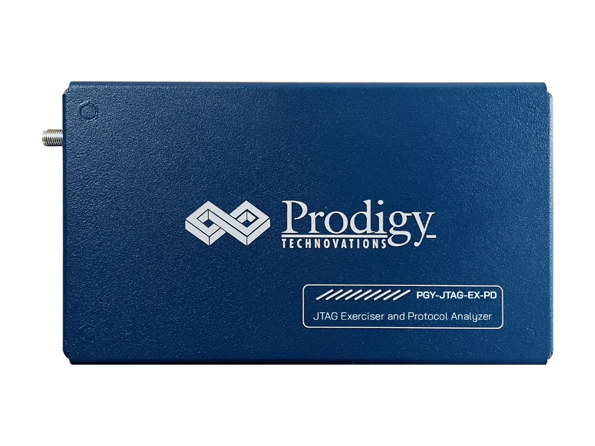
The Prodigy JTAG Protocol Exerciser and Analyzer (PGY-JTAG-EX-PD) generates and decodes JTAG traffic to validate a design’s JTAG port against its specification. As JTAG master it drives TCK from 100 kHz to 25 MHz with adjustable duty cycle, delays and voltage, while decoding TCK, TMS, TDI and TDO on the same bus at the same time. Scripts combine instruction and data writes at different speeds, so timing margins and corner cases can be tested and repeated. Pertech is the authorized Prodigy distributor.

JTAG analyzer or JTAG debug probe?

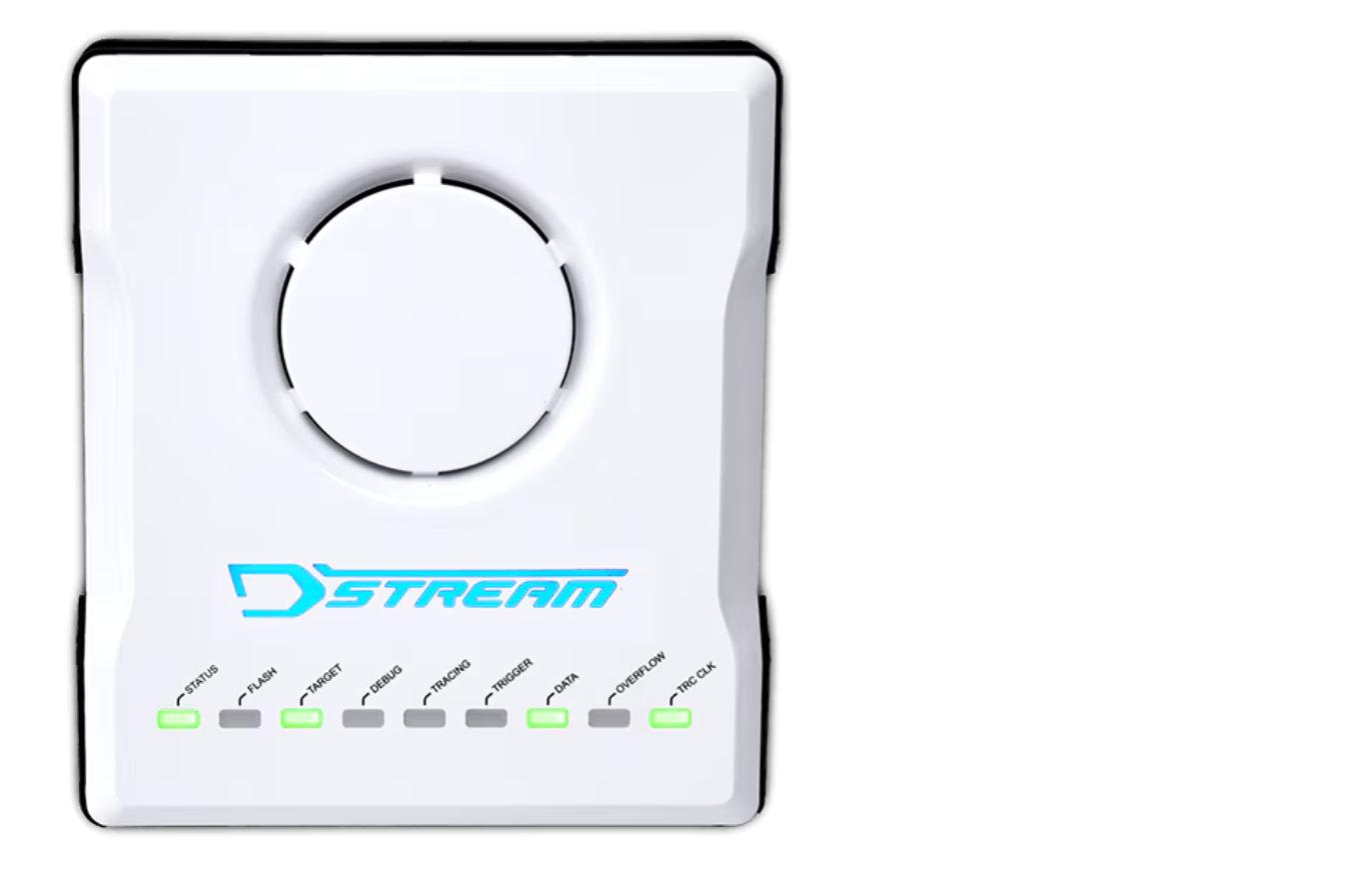
A JTAG debug probe connects an IDE to a processor so you can debug software. This instrument tests the JTAG interface itself: it drives the port with controlled timing and decodes every transition. For software debugging of Arm devices, see the Arm Keil ULINK family and Arm DSTREAM-ST.

JTAG analyzer highlights

  • JTAG master with custom traffic generation from the GUI or scripts
  • TCK from 100 kHz to 25 MHz, duty cycle of 25, 50 or 75 percent
  • Drive levels of 1.2, 1.8 and 3.3 V
  • User-defined TCK to TDI and TCK to TMS delays, and delay between messages
  • Generates traffic and decodes the bus simultaneously, with continuous streaming to the host disk
  • Timing view of TCK, TMS, TDI and TDO with a bus diagram, and a protocol listing correlated to the waveform
  • Error analysis in the decoded protocol
  • Python and C++ API for automation

Where the JTAG analyzer earns its keep

  • Validating the JTAG test access port of new ASICs, FPGAs and SoCs
  • Measuring timing margins by sweeping TCK speed, duty cycle and signal delays
  • Scripted, repeatable instruction and data register sequences for regression testing
  • Decoding the traffic between an existing debugger or tester and the target to find where a sequence fails

Key Specifications

SpecValue
ModelPGY-JTAG-EX-PD
Configuration1 master
TCK frequency100 kHz to 25 MHz
Drive level1.2, 1.8 and 3.3 V
Duty cycle25, 50 or 75%
DelaysUser-defined TCK-TDI, TCK-TMS and between messages
Protocol viewsTiming diagram, protocol listing, bus diagram
CaptureContinuous streaming to host HDD or SSD
APIPython and C++
Host connectionUSB 2.0/3.0

Frequently asked questions

What is a JTAG protocol analyzer used for?

It captures and decodes JTAG traffic so engineers can see each TAP transition, instruction and data transfer, and find where a sequence or its timing breaks. With the exerciser, the same unit also drives the port with controlled traffic.

What TCK speeds does the Prodigy JTAG analyzer support?

TCK runs from 100 kHz to 25 MHz, with a 25, 50 or 75 percent duty cycle and user-defined TCK to TDI and TCK to TMS delays.

Can JTAG sequences be scripted?

Yes. Scripts set frequency, duty cycle and delays, then issue instruction writes, data writes and IR reads, combining frames at different speeds. A Python and C++ API supports full automation.

Is this a replacement for a JTAG debugger?

No. A debugger such as an Arm ULINK or DSTREAM probe is for debugging software through JTAG. The Prodigy instrument validates the JTAG interface and its timing, and decodes traffic from any source.

Where can I buy the Prodigy JTAG analyzer in Israel?

Pertech is the authorized Prodigy distributor. Prodigy offers evaluation units, free online technical support and free software updates. Contact Pertech for a quote or a demo.

Related Prodigy products at Pertech

Validating a JTAG port? Contact Pertech for a quote, a demo or help choosing the right tool.
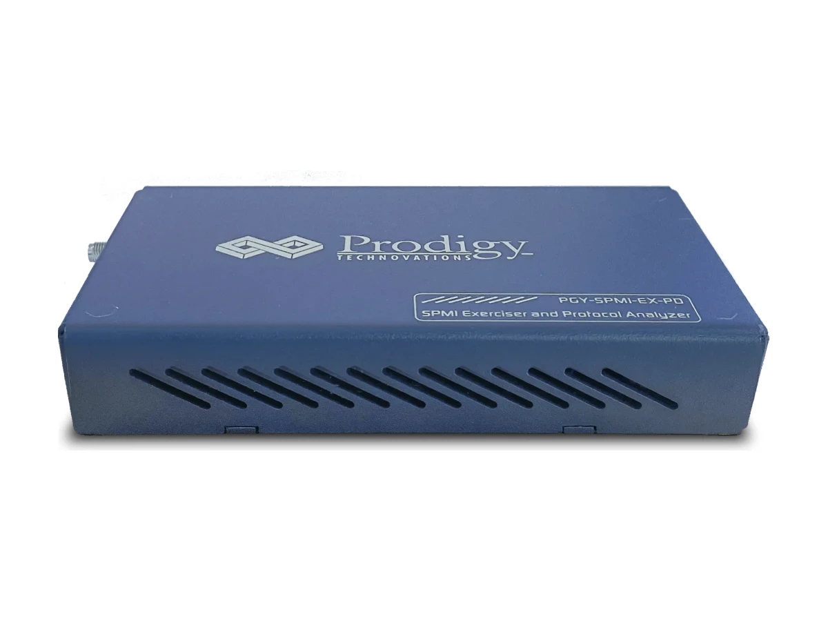

SPMI Protocol Analyzer and Exerciser

The Prodigy SPMI Protocol Analyzer and Exerciser (PGY-SPMI-EX-PD) tests the System Power Management Interface, the MIPI two-wire bus that connects a SoC’s power controller to one or more PMICs. It acts as master or slave, generates SPMI traffic with timing variations and error injection, and decodes SPMI 1.0 and 2.0 packets at bus speeds from 32 kHz to 26 MHz, all at the same time. Pertech is the authorized Prodigy distributor.

SPMI analyzer highlights

  • Supports SPMI 1.0 and 2.0, sole-master and multi-master networks, Request Capable Slaves and bus arbitration
  • Configurable as 1 master and 2 slaves, generating custom SPMI traffic from the GUI or scripts
  • SCLK from 32 kHz to 26 MHz, drive levels of 1.2 or 1.8 V, duty cycle of 25, 50 or 75 percent
  • SCLK and SDATA delays at 4 ns resolution, and adjustable delay between messages
  • Error injection: data, command and address parity, ACK and NACK errors, and Skip SSC in sole-master systems
  • Generates traffic and decodes the bus simultaneously, with continuous streaming to the host disk
  • Timing diagram, protocol listing and bus diagram views with error analysis
  • Python and C++ API, plus optional PICS (Protocol Implementation Compliance Statement) scripts

Where the SPMI analyzer earns its keep

  • PMIC bring-up and validation against the SPMI 1.0 and 2.0 specifications
  • SoC power controller firmware development, with the exerciser standing in for a missing PMIC or master
  • Testing arbitration and Request Capable Slave behavior on multi-master buses
  • Checking that devices detect and recover from parity and acknowledge errors

Key Specifications

SpecValue
ModelPGY-SPMI-EX-PD
SpecificationSPMI 1.0 and 2.0
Configuration1 master + 2 slaves
SCLK frequency32 kHz to 26 MHz
Drive level1.2 or 1.8 V
Duty cycle25, 50 or 75%
Timing resolution4 ns (SCLK and SDATA delay)
Error injectionData, command and address parity; ACK/NACK; Skip SSC (sole master)
TriggersUser-defined SPMI packet after SSC
CaptureContinuous streaming to host
APIPython and C++
Host connectionUSB 2.0/3.0

Frequently asked questions

What is SPMI used for?

SPMI (System Power Management Interface) is a MIPI standard: a two-wire synchronous, bidirectional serial bus that links the power controller in a SoC to one or more PMICs that regulate its supply voltages.

Does the analyzer support SPMI 2.0?

Yes. It supports both SPMI 1.0 and SPMI 2.0, in sole-master and multi-master networks, and the unit can be upgraded as the specification evolves.

Which errors can it inject?

As master it injects data, command and address parity errors and, in sole-master systems, Skip SSC errors; as slave it injects data parity errors. It also reports ACK and NACK errors it sees on the bus.

Can SPMI tests be automated?

Yes. Traffic can be scripted, including multiple frames at different data speeds, and the instrument has a Python and C++ API. Optional PICS scripts support compliance testing.

Where can I buy the Prodigy SPMI analyzer in Israel?

Pertech is the authorized Prodigy distributor. Prodigy offers evaluation units, free online technical support and free software updates. Contact Pertech for a quote or a demo.

Related Prodigy products at Pertech

Validating a PMIC or power controller? Contact Pertech for a quote, a demo or help choosing the right tool.
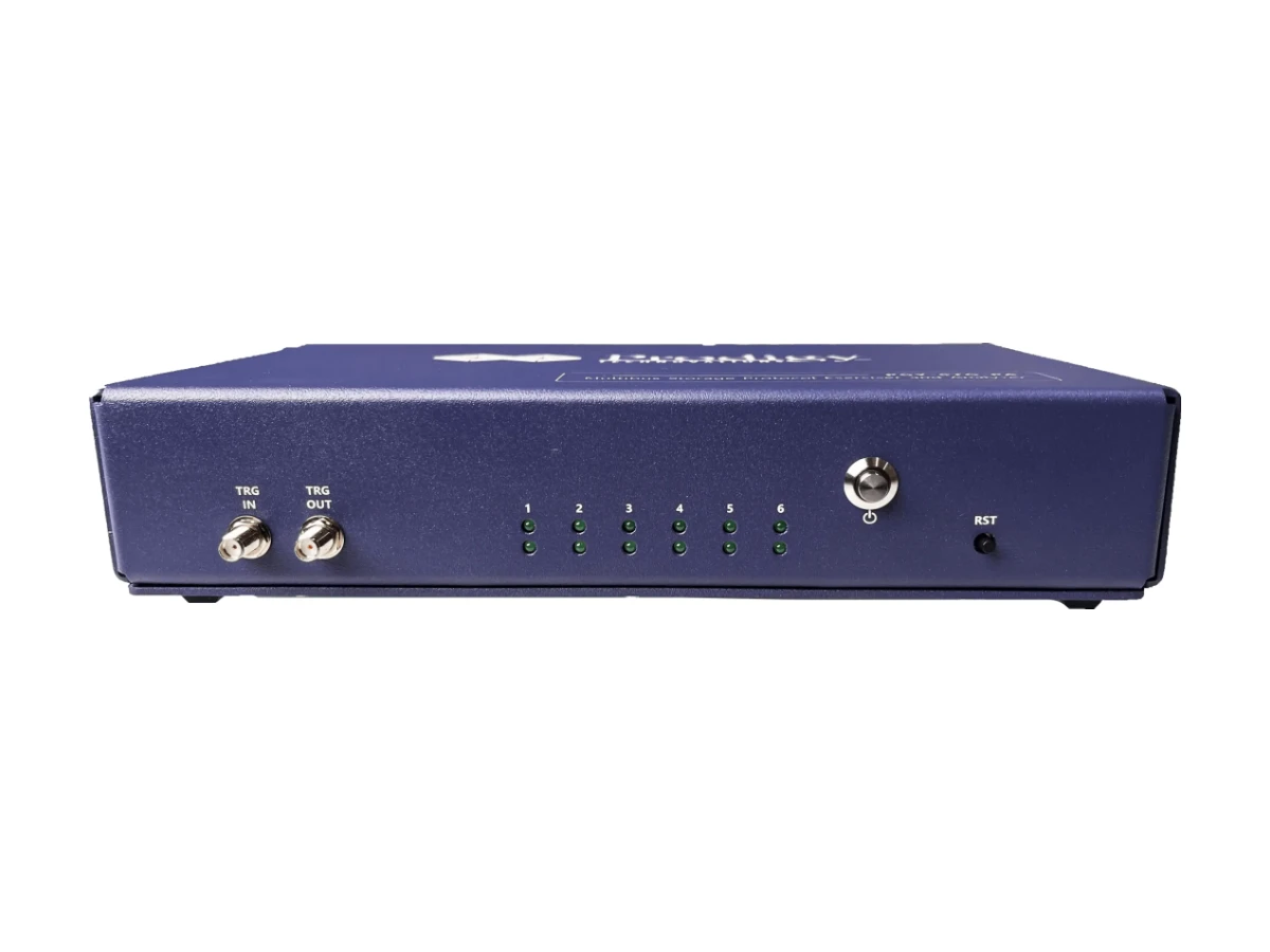

xSPI Protocol Exerciser and Analyzer

The Prodigy xSPI Protocol Exerciser and Analyzer (PGY-STG-PAXSPI) validates and debugs the protocol layer of xSPI and Octal SPI (OSPI) flash and memory interfaces. It captures commands, responses and data at up to 250 MHz in DDR mode through an active probe that puts minimal load on the device under test, and streams the protocol data continuously to the host. A capture can run from power-on through a full transfer, including the switch from single-lane to eight-lane mode, with errors flagged as they happen. Pertech is the authorized Prodigy distributor.

xSPI analyzer highlights

  • Captures commands, responses and data in both 1S-1S-1S and 8S-8S-8S modes
  • Data capture at 250 MHz in DDR mode, with continuous streaming to the host SSD or HDD for long captures
  • Hardware protocol-aware triggers: auto, message and advanced if-then-else multi-level triggers
  • On-the-fly validation of the expected command and response sequence
  • Decodes command, response, CRC, data, arguments and device registers, with analytics and statistics views
  • Monitors two devices at once, at 1.2, 1.8 or 3.3 V
  • Trigger out to start an oscilloscope, and a digital input to mark events in the capture
  • Upgradable to QSPI, eMMC, SD and SDIO protocol analysis

Where the xSPI analyzer earns its keep

  • Bring-up of xSPI and Octal SPI flash and memory controllers in SoCs and MCUs
  • Debugging what happens on the bus from power-on, including the change from one lane to eight lanes
  • Hunting intermittent CRC and sequence errors that need hours of continuous capture
  • Storage teams that want one platform they can extend to QSPI, eMMC and SD

Key Specifications

SpecValue
ModelPGY-STG-PAXSPI
InterfacesxSPI and OSPI
Data captureUp to 250 MHz (DDR)
Data decode1-bit and 8-bit
Protocol decodeCommand, response, CRC, data, arguments, device registers
Operating voltage1.2, 1.8 and 3.3 V
Simultaneous devicesTwo
CaptureContinuous streaming to host storage; manual run/stop or time-specific
TriggersCommand, response, if-then-else multi-level; trigger out
Host interfaceUSB 3.0
ExportTXT, reports

Frequently asked questions

Which interfaces does the Prodigy xSPI analyzer support?

It supports xSPI and Octal SPI (OSPI), decoding 1-bit and 8-bit data in 1S-1S-1S and 8S-8S-8S modes at up to 250 MHz. The same hardware can be upgraded to QSPI, eMMC, SD and SDIO protocol analysis.

Can it capture the boot sequence from power-on?

Yes. The analyzer captures xSPI activity from the power-on state through a full transfer, including the device switching from one lane to eight lanes, and streams it continuously to the host so nothing is lost.

Can it trigger other instruments?

Yes. A trigger out signal fires on any chosen protocol event, so an oscilloscope can capture the electrical waveform at the exact moment of a protocol error.

How does it find protocol errors?

It validates the sequence of commands and responses on the fly and reports any failure, and its search and filter tools jump straight to the packets of interest in a long capture.

Where can I buy the Prodigy xSPI analyzer in Israel?

Pertech is the authorized Prodigy distributor. Prodigy offers evaluation units, free online technical support and free software updates. Contact Pertech for a quote or a demo.

Related Prodigy products at Pertech

Bringing up an octal flash interface? Contact Pertech for a quote, a demo or help choosing the right tool.
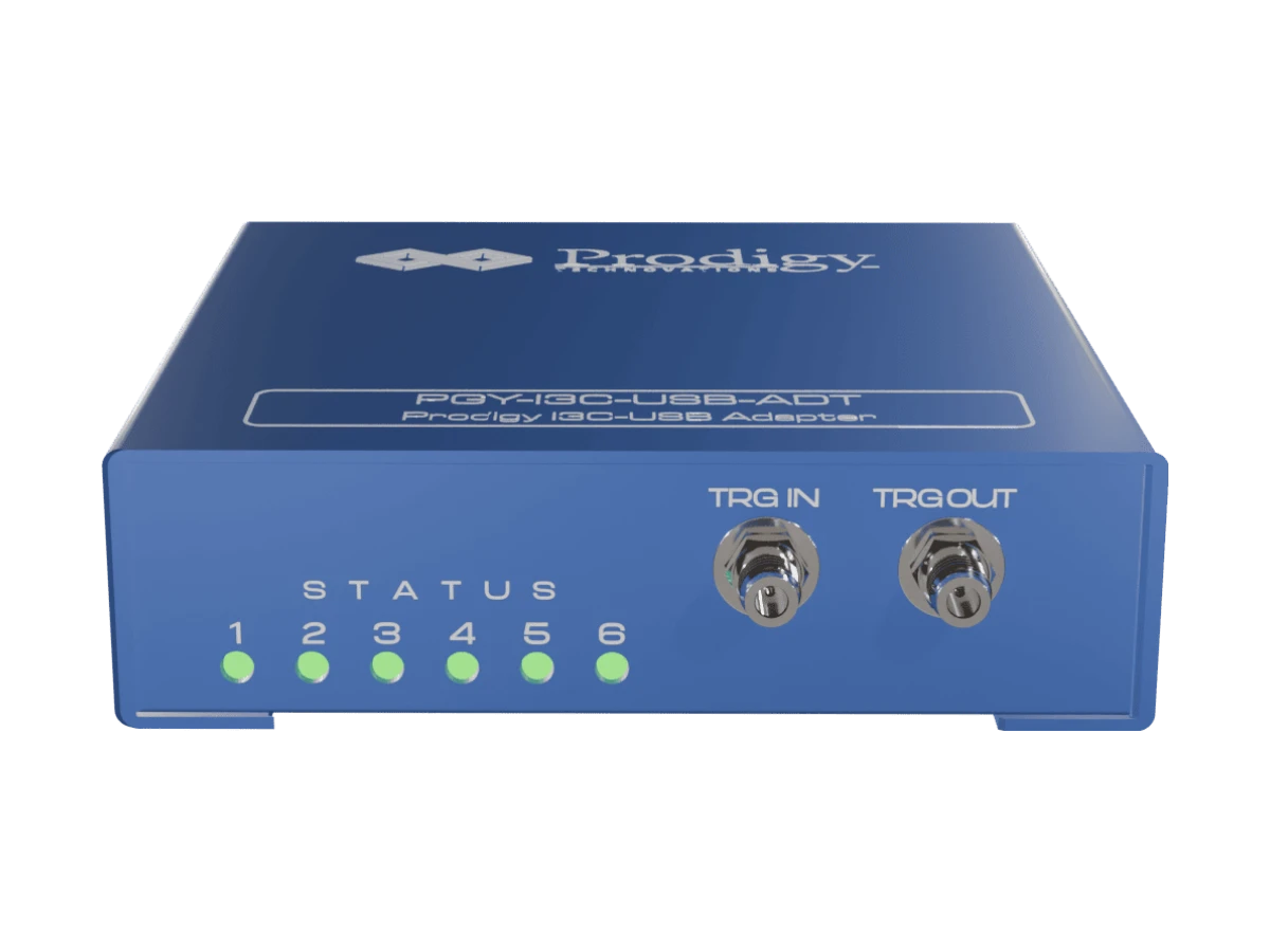

I3C USB Adapter

The Prodigy I3C USB Adapter (PGY-I3C-USB-ADT) puts an I3C bus under the control of your own software. Configuring a controller or target, generating I3C and I2C traffic, monitoring the bus and producing reports are all available through a high-level API on Windows and Linux, so the adapter drops straight into test scripts and production stations. Prodigy positions it as its I3C production test solution, at about a fifth of the price of its full I3C analyzer. Pertech is the authorized Prodigy distributor.

I3C USB Adapter highlights

  • Full API access for third-party applications, with Python support on Windows and Linux
  • One controller and one target, with custom I3C and I2C traffic generation and real-world traffic simulation
  • SCL up to 12.5 MHz, at fixed I/O levels of 1.0, 1.2, 1.8, 2.5 and 3.3 V
  • Clock-to-data delay (tCO) adjustable in 10 ns steps, and adjustable delay between messages
  • All Common Command Codes (CCCs) on the controller side, per I3C v1.0
  • Bus monitoring at 4 ns resolution with continuous streaming to the host disk
  • Error reporting for S0 to S5 errors, CRC errors in HDR-DDR, ACK and NACK errors and controller abort

Where the I3C USB Adapter earns its keep

  • Production test stations that program, configure or check I3C devices from a script
  • Automated regression testing of I3C firmware on Windows or Linux
  • Labs that need a scriptable I3C controller and target on a limited budget

What’s in the box

  • PGY-I3C-USB-ADT unit
  • USB 3.0 cable
  • Flying-lead probe cables with female connectors for the device under test
  • PGY-I3C-USB-ADT software

Choosing between Prodigy’s I3C tools

The full analyzer is Prodigy’s performance option for silicon validation, the I3C Lite covers development and field work, and the USB Adapter is built for scripted production test.

Prodigy I3C tools compared

FeaturePGY-I3C-EX-PDPGY-I3C-LitePGY-I3C-USB-ADT
Configuration1 controller + 3 targets1 controller + 1 target1 controller + 1 target
I/O voltage0.9 to 3.4 V, adjustableFixed 1.0, 1.2, 1.8, 2.5, 3.3 VFixed 1.0, 1.2, 1.8, 2.5, 3.3 V
Error injectionYesNoNo
Hardware protocol-aware triggerYesYesNo
I3C conformance test suiteYesNoNo
APIPython and C++Optional (Python)Yes, Windows and Linux
Typical usePost-silicon validation, pre-silicon traffic generationFirmware development, field and application engineeringProduction test
Relative price (Prodigy)X0.5X0.2X

Key Specifications

SpecValue
ModelPGY-I3C-USB-ADT
I3C specificationv1.0
Configuration1 controller + 1 target
Traffic generationCustom I3C and I2C, real-world traffic simulation
SCL frequencyUp to 12.5 MHz
I/O voltageFixed 1.0, 1.2, 1.8, 2.5, 3.3 V
Monitoring resolution4 ns
CaptureContinuous streaming to host HDD or SSD
APIPython; Windows and Linux
Host connectionUSB 2.0/3.0

Frequently asked questions

What is an I3C USB adapter?

It connects a computer to an I3C bus so software can generate, monitor and control I3C communication. The Prodigy PGY-I3C-USB-ADT exposes all of its functions through an API, which makes it suited to test scripts and production stations.

Which operating systems and languages are supported?

The API runs on Windows and Linux, with Python support, so third-party applications and test frameworks can drive the adapter directly.

Which I3C specification version does it support?

The I3C USB Adapter supports the I3C v1.0 specification, with all Common Command Codes on the controller side.

How is it different from the Prodigy I3C Lite?

Both offer one controller and one target and the same traffic generation. The I3C Lite is a bench and field tool with a GUI and hardware protocol triggers; the USB Adapter is the API-first option for automated and production test, at about 40 percent of the Lite’s price.

Where can I buy the Prodigy I3C USB Adapter in Israel?

Pertech is the authorized Prodigy distributor. Contact Pertech for a quote or a demo.

Related Prodigy products at Pertech

Automating I3C test? Contact Pertech for a quote, a demo or help integrating the adapter into your test station.


I3C Protocol Exerciser and Analyzer Lite

The Prodigy I3C Protocol Exerciser and Analyzer Lite (PGY-I3C-Lite) is a compact, portable I3C tool that both generates and captures bus traffic. Set it up as an I3C controller or target, send custom I3C and I2C transactions at SCL rates up to 12.5 MHz, and decode the bus live at 4 ns resolution with timing, listing and bus diagram views. It brings the core of Prodigy’s I3C exerciser and analyzer to firmware developers and field engineers at about half the price of the full model. Pertech is the authorized Prodigy distributor.

I3C Lite highlights

  • Exerciser: one controller and one target, custom I3C and I2C traffic generation, SCL up to 12.5 MHz
  • Fixed I/O levels of 1.0, 1.2, 1.8, 2.5 and 3.3 V
  • Hot-Join and in-band interrupts (IBI) supported
  • Clock-to-data delay (tCO) adjustable in 10 ns steps, and adjustable delay between messages
  • All Common Command Codes (CCCs) on the controller side, per I3C v1.0
  • Analyzer: I3C and I2C decode at 4 ns resolution, auto and message triggers, continuous streaming to the host disk for long captures
  • Error reporting for S0 to S5 errors, CRC and preamble errors in HDR-DDR, ACK and NACK errors and controller abort
  • PDF and CSV reports with images, offline analysis of saved traces, and an optional Python API

Where the I3C Lite earns its keep

  • Firmware development for I3C sensors, controllers and peripherals
  • Field and application engineers who need an I3C tool they can carry to a customer site
  • Emulating a missing controller or target during system design and validation
  • Teams moving from I2C to I3C who need to see both protocols on the same bus

Choosing between Prodigy’s I3C tools

Prodigy offers three I3C instruments. The full analyzer is the performance option for silicon validation, the Lite covers development and field work, and the I3C USB Adapter is built for scripted production test.

Prodigy I3C tools compared

FeaturePGY-I3C-EX-PDPGY-I3C-LitePGY-I3C-USB-ADT
Configuration1 controller + 3 targets1 controller + 1 target1 controller + 1 target
I/O voltage0.9 to 3.4 V, adjustableFixed 1.0, 1.2, 1.8, 2.5, 3.3 VFixed 1.0, 1.2, 1.8, 2.5, 3.3 V
Error injectionYesNoNo
Hardware protocol-aware triggerYesYesNo
I3C conformance test suiteYesNoNo
APIPython and C++Optional (Python)Yes, Windows and Linux
Typical usePost-silicon validation, pre-silicon traffic generationFirmware development, field and application engineeringProduction test
Relative price (Prodigy)X0.5X0.2X

Key Specifications

SpecValue
ModelPGY-I3C-Lite
Configuration1 controller + 1 target
Traffic generationCustom I3C and I2C
SCL frequencyUp to 12.5 MHz
I/O voltageFixed 1.0, 1.2, 1.8, 2.5, 3.3 V
Hot-Join and IBISupported
Analyzer resolution4 ns
Protocol viewsTiming diagram, protocol listing, bus diagram
TriggersAuto and message trigger
CaptureContinuous streaming to host HDD or SSD
APIPython (optional)
Host connectionUSB 2.0/3.0
ReportsPDF and CSV

Frequently asked questions

What is the difference between an I3C analyzer and an exerciser?

An analyzer captures and decodes the traffic already on the bus. An exerciser generates controlled traffic to see how a device responds. The PGY-I3C-Lite does both, so you can drive a transaction and watch the result in the same session.

How does the Lite compare with the full Prodigy I3C analyzer?

The Lite keeps controller and target emulation, I3C and I2C traffic generation, Hot-Join and IBI, hardware triggers and continuous capture, in a portable unit at about half the price. The full PGY-I3C-EX-PD adds three targets, adjustable voltage and timing, error injection, advanced multi-level triggers and the I3C conformance test suite.

Does the I3C Lite also handle I2C?

Yes. It generates and decodes both I3C and I2C traffic, which helps on mixed buses and during migration from I2C to I3C.

Can I analyze captures later, away from the bench?

Yes. Traffic streams continuously to the host disk, saved traces reload into the software for offline analysis, and reports export to PDF and CSV with images attached.

Where can I buy the Prodigy I3C Lite in Israel?

Pertech is the authorized Prodigy distributor. Prodigy offers evaluation units, free online technical support and free software updates. Contact Pertech for a quote or a demo.

Related Prodigy products at Pertech

Working on an I3C design? Contact Pertech for a quote, a demo or help choosing the right I3C tool.

UFS 5.0 Protocol Exerciser and Analyzer

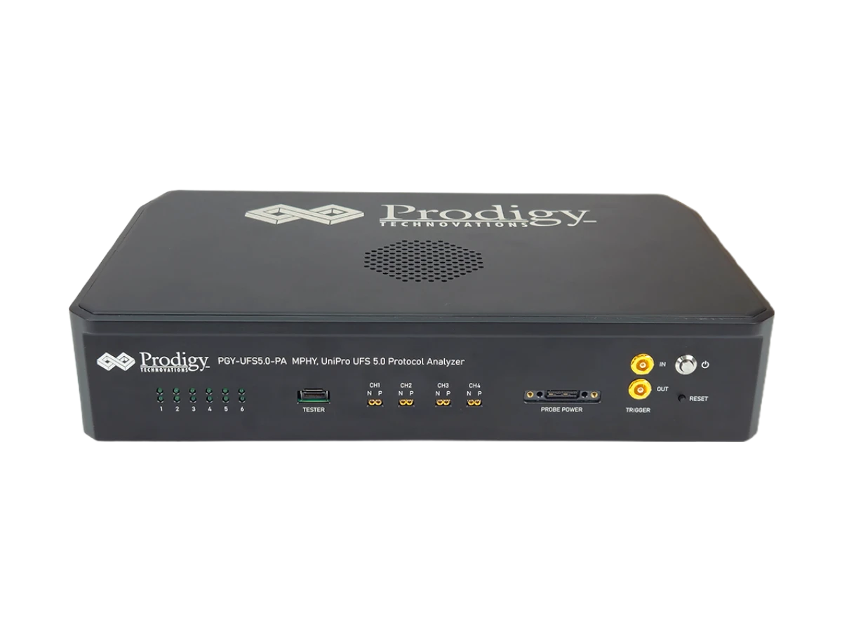
The Prodigy UFS 5.0 Protocol Exerciser and Analyzer (PGY-UFS5.0-EX-PA) captures and decodes the conversation between a UFS host and device from PWM G1 up to HS-G6 Rate B, 46.64 Gbps per lane with PAM4 signaling. It decodes the M-PHY, UniPro and UFS layers at once and correlates them, so a link problem can be followed from the physical layer up to the command that failed. Prodigy has tested it on a real UFS 5.0 device at HS-G6B, and one analyzer covers UFS 2.x through UFS 5.0. Pertech is the authorized Prodigy distributor.

Why UFS 5.0 needs a new analyzer

UFS 5.0 moves storage to HS-G6 and PAM4 signaling, with bandwidth of up to 10.8 GB/s for the on-device AI workloads in phones, wearables, PCs and edge devices. At these rates signal integrity decides whether a capture works at all. The PGY-UFS5.0-EX-PA tunes the CTLE equalization of its probe automatically: it watches eye height and eye width in the software and, when the eye is too closed for a reliable capture, adjusts the redriver settings over SPI until it opens. No manual tuning per board.

UFS 5.0 analyzer highlights

  • PWM G1 and HS-G1 to HS-G6, Rate A and Rate B, on one or two lanes (2 TX and 2 RX)
  • Decodes M-PHY 3.0 to 6.0, PACP, UniPro 1.6 to 3.0 and UFS 2.x to 5.0, with correlation across layers
  • Protocol-aware triggering on UniPro, PACP and UFS packets, plus trigger in and trigger out
  • 16 GB capture buffer, upgradable to 32 GB, with live, post-acquisition and circular modes
  • Automatic protocol validation: CRC error count, sequence number mismatch, PACP request and confirm mismatch, command and response mismatch
  • Separate PACP view for power mode changes, with search, filter-in and filter-out at packet or field level
  • Optional UFS 5.0 host and device emulation, including UFS 5.0 and UniPro conformance test suites

Where the UFS 5.0 analyzer earns its keep

  • Bring-up and validation of UFS 5.0 controllers, devices and SoCs for smartphones, wearables, PCs and edge AI
  • Teams moving from UFS 4.x to UFS 5.0 who want one instrument for both generations
  • Debugging HS link-up, power mode changes and command and response errors between host and device
  • Conformance testing against the UFS and UniPro test suites with host emulation

Key Specifications

SpecValue
ModelPGY-UFS5.0-EX-PA
Data ratesPWM G1; HS-G1 to HS-G6, Rate A and B (up to 46.64 Gbps per lane, PAM4)
Lanes1TX/1RX or 2TX/2RX
Protocol layersM-PHY 3.0/4.0/5.0/6.0, PACP, UniPro 1.6/1.8/2.0/3.0, UFS 2.x/3.x/4.x/5.0
Capture buffer16 GB, upgradable to 32 GB
TriggersAuto, UniPro, PACP and UFS packet; trigger in/out
Probes and interposersSolder-down active probes, board-to-board interposer, active power divider interposer, mSMP connector based probe
Signal conditioningAutomatic CTLE tuning
Emulation (optional)UFS 5.0 host and device
Host interfaceUSB 3.0 Type-C
ReportsCSV
ComplianceCE and RoHS (self-certified)

Frequently asked questions

Does the UFS 5.0 analyzer also work with UFS 4.x devices?

Yes. It supports UFS 2.x through UFS 5.0, and its default probe equalization settings suit a wide range of UFS 4.x devices, so one instrument covers current designs and the move to UFS 5.0.

How is it different from the Prodigy UFS 4.0/4.1 analyzer?

The UFS 4.0/4.1 analyzer runs up to HS-G5 Rate B. The UFS 5.0 model adds HS-G6 Rate B at 46.64 Gbps per lane with PAM4 signaling, M-PHY 6.0 and UniPro 3.0 decode, automatic CTLE tuning, and optional UFS 5.0 host and device emulation.

Can it emulate a UFS host or device?

Yes, as an option. Host emulation runs the UFS 5.0 and UniPro conformance test suites and custom test cases. Device emulation generates HS-G6 Rate A and Rate B traffic and responds to HS link-up, read and write operations, using an FPGA PHY (no M-PHY).

How do I connect it to my design?

Prodigy offers solder-down active probes for data rates up to HS-G6B, a board-to-board interposer and an active power divider interposer up to 46.64 Gbps, and an mSMP connector based probe.

Where can I buy the Prodigy UFS 5.0 analyzer in Israel?

Pertech is the authorized Prodigy distributor. Prodigy offers evaluation units, free online technical support and free software updates. Contact Pertech for a quote or a demo.

Related Prodigy products at Pertech

Validating UFS 5.0? Contact Pertech for a quote, a demo or help choosing probes for your board.


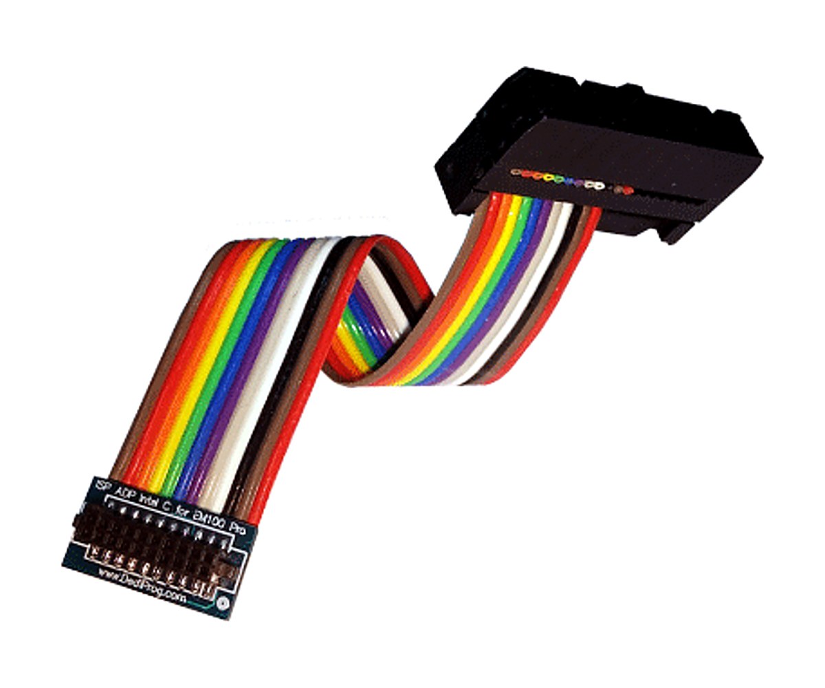
Intel ISP Adaptor-C2 for EM100Pro and SF600 series – ISP-ADP-INTEL-C2

Intel ISP Adaptor-C2 for EM100Pro and SF600 series – ISP-ADP-INTEL-C2

Connect an EM100Pro or SF600 to Intel motherboards

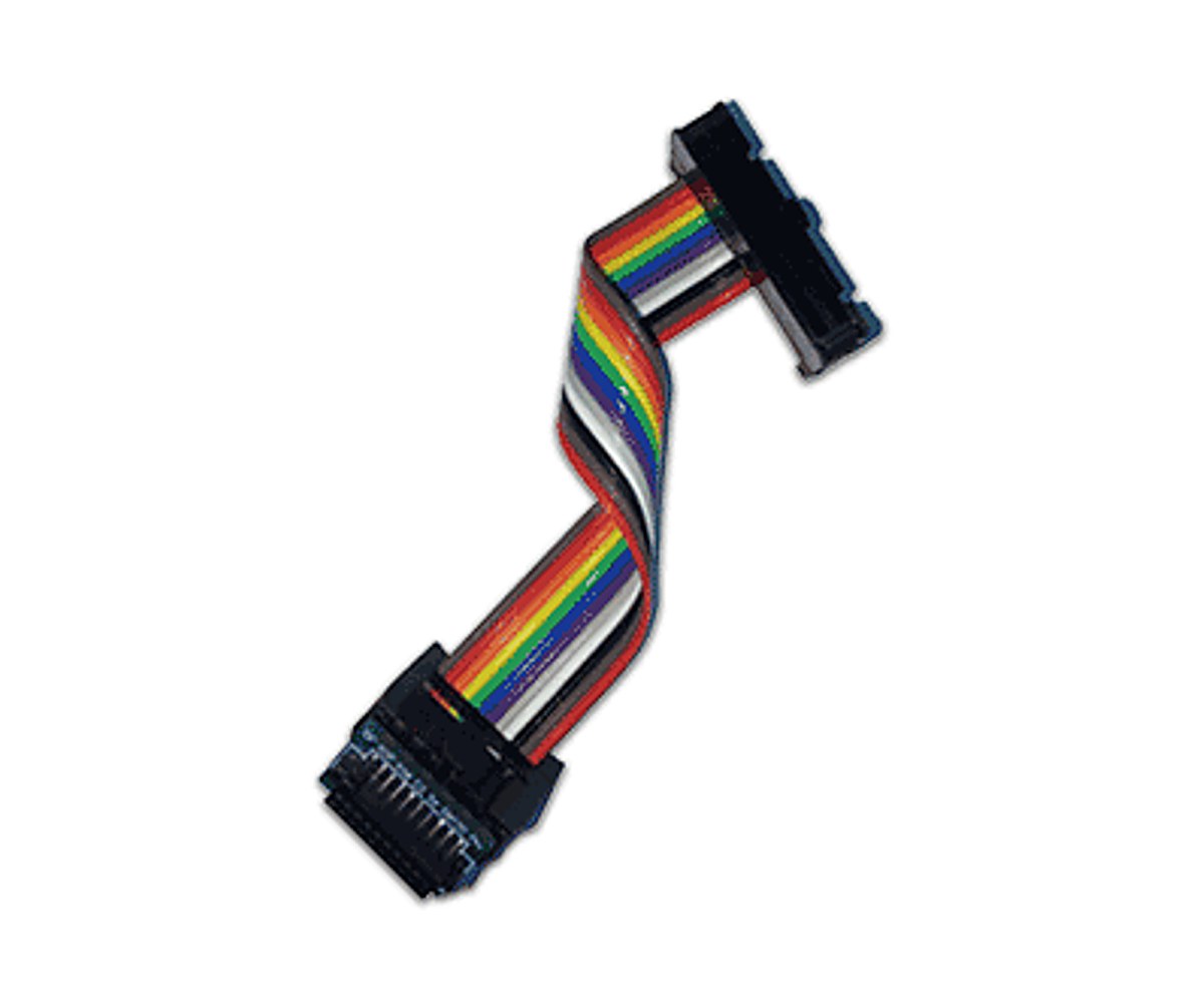
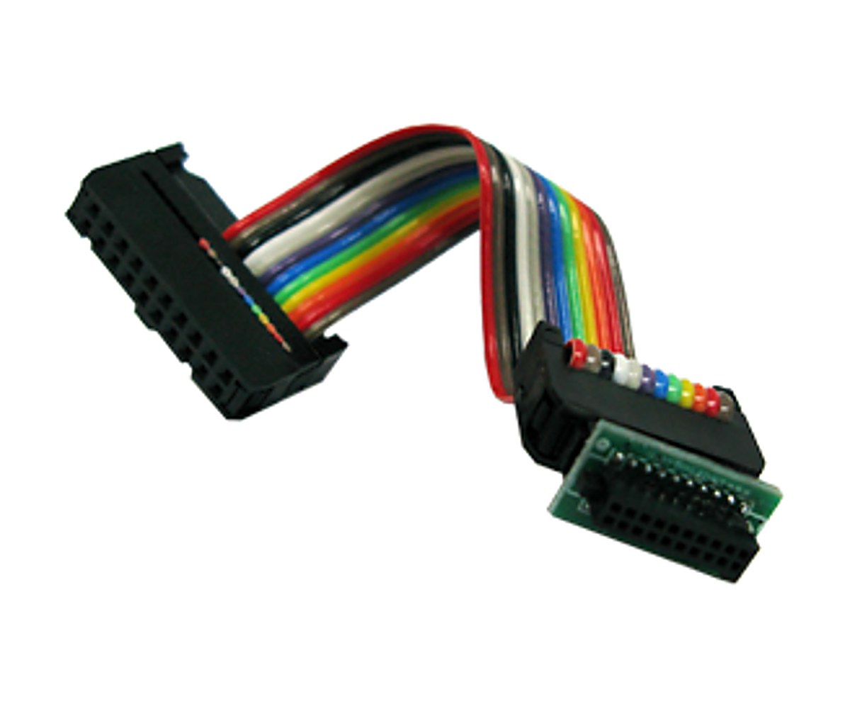
The ISP-ADP-INTEL-C2 connects a DediProg EM100Pro, EM100Pro-G2, EM100Pro-G3, SF600, SF600Plus and SF600Plus-G2 to the 2×10 SPI flash programming header on Intel motherboards, so you can program or emulate the board’s SPI flash in-system. It supports Quad I/O.

It mates with Intel’s 2×10 connector (Samtec ASP-159358-02 or TFM-110-02-S-D-A) and comes on a cable about 8 cm long. The cable plugs into the adaptor through a connector, so you can detach it from the adaptor. Apart from the cable, it works the same as the ISP-ADP-INTEL-C.

Highlights

  • Connects the EM100Pro, EM100Pro-G2, EM100Pro-G3, SF600, SF600Plus and SF600Plus-G2 to Intel motherboards
  • Mates with the Intel 2×10 header (Samtec ASP-159358-02 or TFM-110-02-S-D-A)
  • Cable about 8 cm long; detachable from the adaptor
  • Quad I/O supported

Adaptor Pin-out (2×10)

PinSignalPinSignal
1KEY2CS0
3RESET4CS1
5GND6VCC
7CLK8DQ2 / WP
9DQ3 / HOLD10MISO
11n/c12MOSI
13-19n/c14-20n/c

Signal Names: EM100Pro series / SF600 series ISP header (2×10) to Adaptor

A few signals carry different names on the programmer header and on the Intel adaptor. They map as follows.

Programmer pinSignalAdaptor pinSignal
2CS24CS1
3CS12CS0
4VCC6VCC

Which Intel ISP Adaptor Do I Need?

A, B and C models have the cable soldered to the adaptor; A2, B2 and C2 models have a detachable cable. Otherwise each pair is the same.

ModelUse withDesign notes
ISP-ADP-INTEL-A / ISP-ADP-INTEL-A2SF100Pull-up resistors on WP and HOLD. Model A also has jumpers tying WP/HOLD to VCC, which can stop some mainboards from booting
ISP-ADP-INTEL-B / ISP-ADP-INTEL-B2SF600, SF600Plus, SF600Plus-G2Pull-up resistors on WP and HOLD. No Quad I/O
ISP-ADP-INTEL-C / ISP-ADP-INTEL-C2EM100Pro, EM100Pro-G2, EM100Pro-G3, SF600, SF600Plus, SF600Plus-G2No resistors or jumpers on any pin. Quad I/O supported. For single I/O programming, the target board needs pull-ups on WP/HOLD

Key Specifications

SpecValue
Part numberISP-ADP-INTEL-C2
Use withEM100Pro, EM100Pro-G2, EM100Pro-G3, SF600, SF600Plus and SF600Plus-G2
Mates withIntel 2×10 header, Samtec ASP-159358-02 or TFM-110-02-S-D-A
CableAbout 8 cm, detachable (connector at the adaptor)
Quad I/OYes
Design notesNo resistors or jumpers on any pin, to keep the signal path clean. For single I/O programming, the target board needs pull-up resistors on WP and HOLD.

In the Box

  • ISP-ADP-INTEL-C2 adaptor with cable

For the programmer, see the EM100Pro-G3 and SF600Plus-G2.

For quantities, lead time or a quote, contact Pertech.

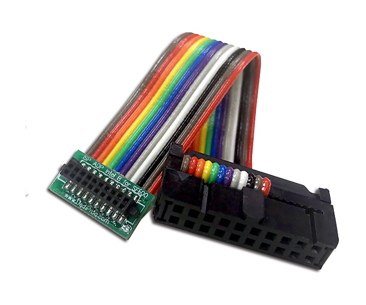
Intel ISP Adaptor-B2 for SF600 series – ISP-ADP-INTEL-B2

Intel ISP Adaptor-B2 for SF600 series – ISP-ADP-INTEL-B2

Connect the SF600 series to Intel motherboards

The ISP-ADP-INTEL-B2 connects a DediProg SF600, SF600Plus and SF600Plus-G2 to the 2×10 SPI flash programming header on Intel motherboards, so you can program or emulate the board’s SPI flash in-system. It does not support Quad I/O; for Quad I/O, use the ISP-ADP-INTEL-C2.

It mates with Intel’s 2×10 connector (Samtec ASP-159358-03) and comes on a cable about 8 cm long. The cable plugs into the adaptor through a connector, so you can detach it from the adaptor. Apart from the cable, it works the same as the ISP-ADP-INTEL-B.

Highlights

  • Connects the SF600, SF600Plus and SF600Plus-G2 to Intel motherboards
  • Mates with the Intel 2×10 header (Samtec ASP-159358-03)
  • Cable about 8 cm long; detachable from the adaptor
  • No Quad I/O

Adaptor Pin-out (2×10)

PinSignalPinSignal
1KEY2CS0
3RESET4CS1
5GND6VCC
7CLK8DQ2 / WP
9DQ3 / HOLD10MISO
11n/c12MOSI
13-19n/c14-20n/c

Signal Names: SF600 / SF600Plus / SF600Plus-G2 ISP header (2×10) to Adaptor

A few signals carry different names on the programmer header and on the Intel adaptor. They map as follows.

Programmer pinSignalAdaptor pinSignal
2CS24CS1
3CS12CS0
4VCC6VCC

Which Intel ISP Adaptor Do I Need?

A, B and C models have the cable soldered to the adaptor; A2, B2 and C2 models have a detachable cable. Otherwise each pair is the same.

ModelUse withDesign notes
ISP-ADP-INTEL-A / ISP-ADP-INTEL-A2SF100Pull-up resistors on WP and HOLD. Model A also has jumpers tying WP/HOLD to VCC, which can stop some mainboards from booting
ISP-ADP-INTEL-B / ISP-ADP-INTEL-B2SF600, SF600Plus, SF600Plus-G2Pull-up resistors on WP and HOLD. No Quad I/O
ISP-ADP-INTEL-C / ISP-ADP-INTEL-C2EM100Pro, EM100Pro-G2, EM100Pro-G3, SF600, SF600Plus, SF600Plus-G2No resistors or jumpers on any pin. Quad I/O supported. For single I/O programming, the target board needs pull-ups on WP/HOLD

Key Specifications

SpecValue
Part numberISP-ADP-INTEL-B2
Use withSF600, SF600Plus and SF600Plus-G2
Mates withIntel 2×10 header, Samtec ASP-159358-03
CableAbout 8 cm, detachable (connector at the adaptor)
Quad I/ONo
Design notesPull-up resistors on WP and HOLD.

In the Box

  • ISP-ADP-INTEL-B2 adaptor with cable

For the programmer, see the SF600Plus-G2 programmer.

For quantities, lead time or a quote, contact Pertech.

Intel ISP Adaptor-C for EM100Pro and SF600 series – ISP-ADP-INTEL-C

Intel ISP Adaptor-C for EM100Pro and SF600 series – ISP-ADP-INTEL-C

Connect an EM100Pro or SF600 to Intel motherboards

The ISP-ADP-INTEL-C connects a DediProg EM100Pro, EM100Pro-G2, EM100Pro-G3, SF600, SF600Plus and SF600Plus-G2 to the 2×10 SPI flash programming header on Intel motherboards, so you can program or emulate the board’s SPI flash in-system. It supports Quad I/O.

It mates with Intel’s 2×10 connector (Samtec ASP-159358-02 or TFM-110-02-S-D-A) and comes on a cable about 8 cm long. The cable is soldered to the adaptor. When you remove it from the mainboard, pull on the adaptor, not on the cable. Apart from the cable, it works the same as the ISP-ADP-INTEL-C2.

Highlights

  • Connects the EM100Pro, EM100Pro-G2, EM100Pro-G3, SF600, SF600Plus and SF600Plus-G2 to Intel motherboards
  • Mates with the Intel 2×10 header (Samtec ASP-159358-02 or TFM-110-02-S-D-A)
  • Cable about 8 cm long; soldered to the adaptor
  • Quad I/O supported

Adaptor Pin-out (2×10)

PinSignalPinSignal
1KEY2CS0
3RESET4CS1
5GND6VCC
7CLK8DQ2 / WP
9DQ3 / HOLD10MISO
11n/c12MOSI
13-19n/c14-20n/c

Signal Names: EM100Pro series / SF600 series ISP header (2×10) to Adaptor

A few signals carry different names on the programmer header and on the Intel adaptor. They map as follows.

Programmer pinSignalAdaptor pinSignal
2CS24CS1
3CS12CS0
4VCC6VCC

Which Intel ISP Adaptor Do I Need?

A, B and C models have the cable soldered to the adaptor; A2, B2 and C2 models have a detachable cable. Otherwise each pair is the same.

ModelUse withDesign notes
ISP-ADP-INTEL-A / ISP-ADP-INTEL-A2SF100Pull-up resistors on WP and HOLD. Model A also has jumpers tying WP/HOLD to VCC, which can stop some mainboards from booting
ISP-ADP-INTEL-B / ISP-ADP-INTEL-B2SF600, SF600Plus, SF600Plus-G2Pull-up resistors on WP and HOLD. No Quad I/O
ISP-ADP-INTEL-C / ISP-ADP-INTEL-C2EM100Pro, EM100Pro-G2, EM100Pro-G3, SF600, SF600Plus, SF600Plus-G2No resistors or jumpers on any pin. Quad I/O supported. For single I/O programming, the target board needs pull-ups on WP/HOLD

Key Specifications

SpecValue
Part numberISP-ADP-INTEL-C
Use withEM100Pro, EM100Pro-G2, EM100Pro-G3, SF600, SF600Plus and SF600Plus-G2
Mates withIntel 2×10 header, Samtec ASP-159358-02 or TFM-110-02-S-D-A
CableAbout 8 cm, soldered to the adaptor
Quad I/OYes
Design notesNo resistors or jumpers on any pin, to keep the signal path clean. For single I/O programming, the target board needs pull-up resistors on WP and HOLD.

In the Box

  • ISP-ADP-INTEL-C adaptor with cable

For the programmer, see the EM100Pro-G3 and SF600Plus-G2.

For quantities, lead time or a quote, contact Pertech.

Intel ISP Adaptor-B for SF600 series – ISP-ADP-INTEL-B

Intel ISP Adaptor-B for SF600 series – ISP-ADP-INTEL-B

Connect the SF600 series to Intel motherboards

The ISP-ADP-INTEL-B connects a DediProg SF600, SF600Plus and SF600Plus-G2 to the 2×10 SPI flash programming header on Intel motherboards, so you can program or emulate the board’s SPI flash in-system. It does not support Quad I/O; for Quad I/O, use the ISP-ADP-INTEL-C.

It mates with Intel’s 2×10 connector (Samtec ASP-159358-03) and comes on a cable about 8 cm long. The cable is soldered to the adaptor. When you remove it from the mainboard, pull on the adaptor, not on the cable. Apart from the cable, it works the same as the ISP-ADP-INTEL-B2.

Highlights

  • Connects the SF600, SF600Plus and SF600Plus-G2 to Intel motherboards
  • Mates with the Intel 2×10 header (Samtec ASP-159358-03)
  • Cable about 8 cm long; soldered to the adaptor
  • No Quad I/O

Adaptor Pin-out (2×10)

PinSignalPinSignal
1KEY2CS0
3RESET4CS1
5GND6VCC
7CLK8DQ2 / WP
9DQ3 / HOLD10MISO
11n/c12MOSI
13-19n/c14-20n/c

Signal Names: SF600 / SF600Plus / SF600Plus-G2 ISP header (2×10) to Adaptor

A few signals carry different names on the programmer header and on the Intel adaptor. They map as follows.

Programmer pinSignalAdaptor pinSignal
2CS24CS1
3CS12CS0
4VCC6VCC

Which Intel ISP Adaptor Do I Need?

A, B and C models have the cable soldered to the adaptor; A2, B2 and C2 models have a detachable cable. Otherwise each pair is the same.

ModelUse withDesign notes
ISP-ADP-INTEL-A / ISP-ADP-INTEL-A2SF100Pull-up resistors on WP and HOLD. Model A also has jumpers tying WP/HOLD to VCC, which can stop some mainboards from booting
ISP-ADP-INTEL-B / ISP-ADP-INTEL-B2SF600, SF600Plus, SF600Plus-G2Pull-up resistors on WP and HOLD. No Quad I/O
ISP-ADP-INTEL-C / ISP-ADP-INTEL-C2EM100Pro, EM100Pro-G2, EM100Pro-G3, SF600, SF600Plus, SF600Plus-G2No resistors or jumpers on any pin. Quad I/O supported. For single I/O programming, the target board needs pull-ups on WP/HOLD

Key Specifications

SpecValue
Part numberISP-ADP-INTEL-B
Use withSF600, SF600Plus and SF600Plus-G2
Mates withIntel 2×10 header, Samtec ASP-159358-03
CableAbout 8 cm, soldered to the adaptor
Quad I/ONo
Design notesPull-up resistors on WP and HOLD.

In the Box

  • ISP-ADP-INTEL-B adaptor with cable

For the programmer, see the SF600Plus-G2 programmer.

For quantities, lead time or a quote, contact Pertech.

Intel ISP Adaptor-A2 for SF100 – ISP-ADP-INTEL-A2

Intel ISP Adaptor-A2 for SF100 – ISP-ADP-INTEL-A2

Connect the SF100 to Intel motherboards

The ISP-ADP-INTEL-A2 connects a DediProg SF100 to the 2×10 SPI flash programming header on Intel motherboards, so you can program or emulate the board’s SPI flash in-system.

It mates with Intel’s 2×10 connector (Samtec ASP-159358-03) and comes on a cable about 8 cm long. The cable plugs into the adaptor through a connector, so you can detach it from the adaptor. Apart from the cable, it works the same as the ISP-ADP-INTEL-A.

Highlights

  • Connects the SF100 to Intel motherboards
  • Mates with the Intel 2×10 header (Samtec ASP-159358-03)
  • Cable about 8 cm long; detachable from the adaptor
  • Pull-up resistors on WP and HOLD

Adaptor Pin-out (2×10)

PinSignalPinSignal
1KEY2CS0
3RESET4CS1
5GND6VCC
7CLK8DQ2 / WP
9DQ3 / HOLD10MISO
11n/c12MOSI
13-19n/c14-20n/c

Signal Names: SF100 ISP header (2×7) to Adaptor

A few signals carry different names on the programmer header and on the Intel adaptor. They map as follows.

Programmer pinSignalAdaptor pinSignal
3I/O2 or CS24CS1
5VCC6VCC
7CS2CS0
12I/O33RESET

Which Intel ISP Adaptor Do I Need?

A, B and C models have the cable soldered to the adaptor; A2, B2 and C2 models have a detachable cable. Otherwise each pair is the same.

ModelUse withDesign notes
ISP-ADP-INTEL-A / ISP-ADP-INTEL-A2SF100Pull-up resistors on WP and HOLD. Model A also has jumpers tying WP/HOLD to VCC, which can stop some mainboards from booting
ISP-ADP-INTEL-B / ISP-ADP-INTEL-B2SF600, SF600Plus, SF600Plus-G2Pull-up resistors on WP and HOLD. No Quad I/O
ISP-ADP-INTEL-C / ISP-ADP-INTEL-C2EM100Pro, EM100Pro-G2, EM100Pro-G3, SF600, SF600Plus, SF600Plus-G2No resistors or jumpers on any pin. Quad I/O supported. For single I/O programming, the target board needs pull-ups on WP/HOLD

Key Specifications

SpecValue
Part numberISP-ADP-INTEL-A2
Use withSF100
Mates withIntel 2×10 header, Samtec ASP-159358-03
CableAbout 8 cm, detachable (connector at the adaptor)
Quad I/ONot stated by DediProg
Design notesPull-up resistors on WP and HOLD. This model also has jumpers that tie WP and HOLD to VCC, which can stop some mainboards from booting; if that happens, consider the A2.

In the Box

  • ISP-ADP-INTEL-A2 adaptor with cable

For the programmer, see the SF100 programmer.

For quantities, lead time or a quote, contact Pertech.

Intel ISP Adaptor-A for SF100 – ISP-ADP-INTEL-A

Intel ISP Adaptor-A for SF100 – ISP-ADP-INTEL-A

Connect the SF100 to Intel motherboards

The ISP-ADP-INTEL-A connects a DediProg SF100 to the 2×10 SPI flash programming header on Intel motherboards, so you can program or emulate the board’s SPI flash in-system.

It mates with Intel’s 2×10 connector (Samtec ASP-159358-03) and comes on a cable about 8 cm long. The cable is soldered to the adaptor. When you remove it from the mainboard, pull on the adaptor, not on the cable. Apart from the cable, it works the same as the ISP-ADP-INTEL-A2.

Highlights

  • Connects the SF100 to Intel motherboards
  • Mates with the Intel 2×10 header (Samtec ASP-159358-03)
  • Cable about 8 cm long; soldered to the adaptor
  • Pull-up resistors on WP and HOLD

Adaptor Pin-out (2×10)

PinSignalPinSignal
1KEY2CS0
3RESET4CS1
5GND6VCC
7CLK8DQ2 / WP
9DQ3 / HOLD10MISO
11n/c12MOSI
13-19n/c14-20n/c

Signal Names: SF100 ISP header (2×7) to Adaptor

A few signals carry different names on the programmer header and on the Intel adaptor. They map as follows.

Programmer pinSignalAdaptor pinSignal
3I/O2 or CS24CS1
5VCC6VCC
7CS2CS0
12I/O33RESET

Which Intel ISP Adaptor Do I Need?

A, B and C models have the cable soldered to the adaptor; A2, B2 and C2 models have a detachable cable. Otherwise each pair is the same.

ModelUse withDesign notes
ISP-ADP-INTEL-A / ISP-ADP-INTEL-A2SF100Pull-up resistors on WP and HOLD. Model A also has jumpers tying WP/HOLD to VCC, which can stop some mainboards from booting
ISP-ADP-INTEL-B / ISP-ADP-INTEL-B2SF600, SF600Plus, SF600Plus-G2Pull-up resistors on WP and HOLD. No Quad I/O
ISP-ADP-INTEL-C / ISP-ADP-INTEL-C2EM100Pro, EM100Pro-G2, EM100Pro-G3, SF600, SF600Plus, SF600Plus-G2No resistors or jumpers on any pin. Quad I/O supported. For single I/O programming, the target board needs pull-ups on WP/HOLD

Key Specifications

SpecValue
Part numberISP-ADP-INTEL-A
Use withSF100
Mates withIntel 2×10 header, Samtec ASP-159358-03
CableAbout 8 cm, soldered to the adaptor
Quad I/ONot stated by DediProg
Design notesPull-up resistors on WP and HOLD. This model also has jumpers that tie WP and HOLD to VCC, which can stop some mainboards from booting; if that happens, consider the A2.

In the Box

  • ISP-ADP-INTEL-A adaptor with cable

For the programmer, see the SF100 programmer.

For quantities, lead time or a quote, contact Pertech.

TSOP56 SMT Socket – 980020-56-P1

TSOP56 SMT Socket – 980020-56-P1

Swap TSOP56 chips without soldering

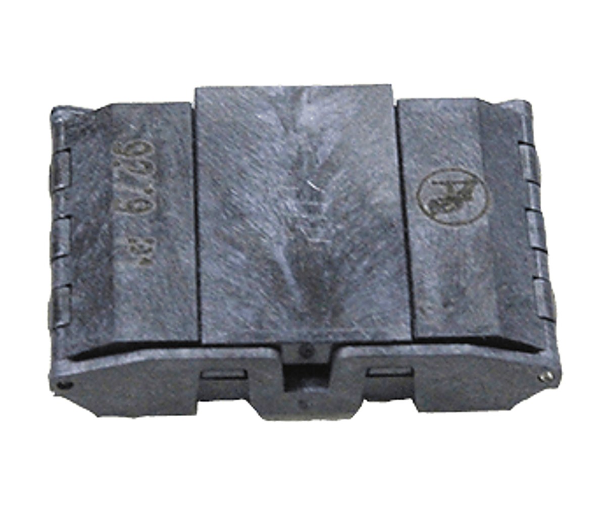
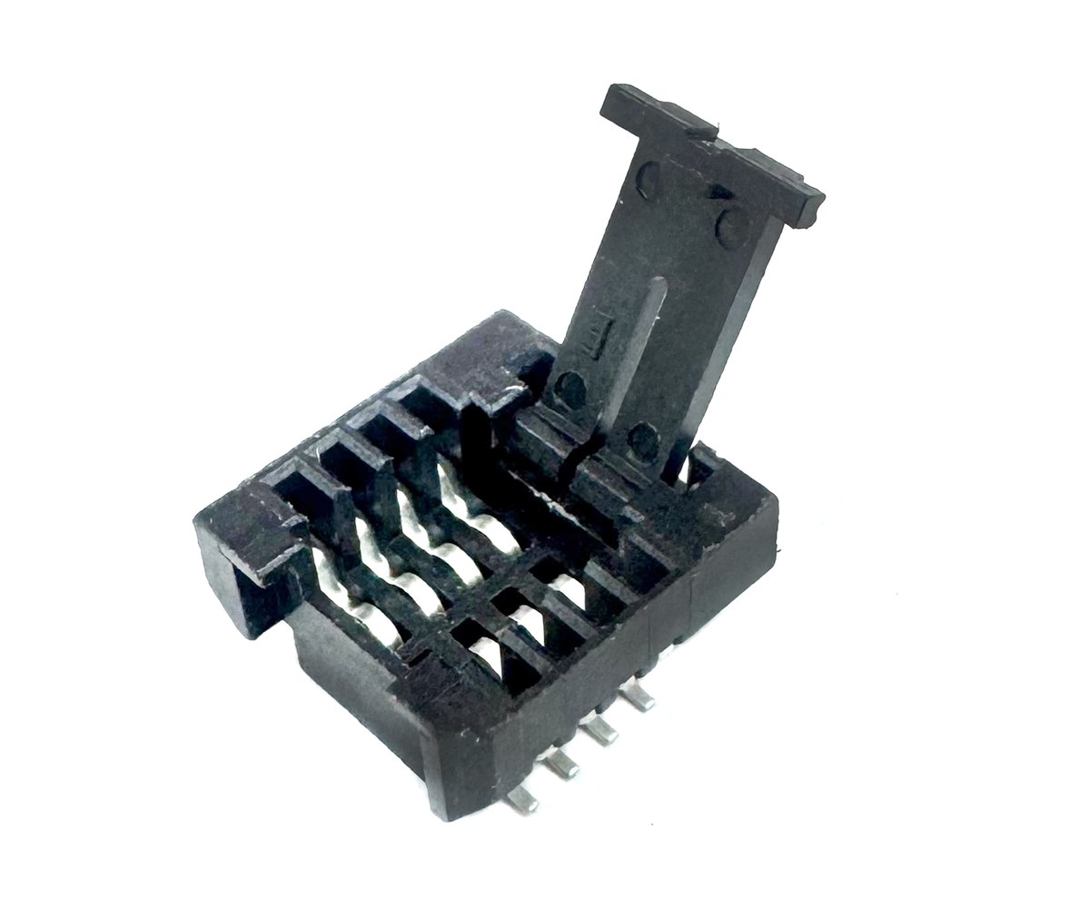
The 980020-56-P1 is a surface-mount socket for chips in the TSOP56 package. It is soldered directly onto the TSOP56 footprint on your board, so during development you no longer need to solder and desolder the chip each time you change it.

To use it, open the socket lid, place the chip and close it again.

Highlights

  • Fits chips in the TSOP56 package
  • Solders directly onto the TSOP56 PCB footprint
  • Open-lid design for placing and removing the chip
  • Ends repeated soldering and desoldering during development

How It Is Used

  • Start with the TSOP56 footprint on your board
  • Solder the socket onto the footprint instead of the chip
  • Open the socket and insert the chip
  • Close the socket; open it again to swap the chip

Key Specifications

SpecValue
Part number980020-56-P1
PackageTSOP56
MountingSurface mount (SMT), on the IC footprint
UseDevelopment and test

In the Box

  • TSOP56 SMT socket

Other DediProg SMT sockets from Pertech: SOK-SPI-8N, SOK-SPI-8W, SOK-SPI-8W-1, SOK-SPI-16W, SOK-SPI-WSON56, SOK-SPI-WSON68-L.

For quantities, lead time or a quote, contact Pertech.

WSON8 6×8 mm SMT Socket – SOK-SPI-WSON68-L

WSON8 6×8 mm SMT Socket – SOK-SPI-WSON68-L

Swap WSON8 SPI flash chips without soldering

The SOK-SPI-WSON68-L is a surface-mount socket for SPI flash chips in the WSON8, 6 x 8 mm package. It is soldered onto the board’s flash footprint in place of the chip. From then on, you drop chips into the socket and take them out again, so you can try different flash parts or reprogram one off-board without reworking the PCB.

DediProg’s specification drawing gives the socket pitch only. If the production board will carry the chip without the socket, plan the pad layout for the chip’s own pin pitch from the start of the PCB design.

Highlights

  • Fits SPI flash in the WSON8, 6 x 8 mm package
  • Solders onto the board in place of the flash chip
  • Chips go in and out without soldering or desoldering
  • PCB layout, specification drawing and 3D model file available from DediProg

How It Is Used

  • Start with the WSON8 footprint on your board
  • Solder the socket onto the footprint instead of the SPI flash
  • Insert the SPI flash chip into the socket
  • Swap or remove the chip whenever you need to

Key Specifications

SpecValue
Part numberSOK-SPI-WSON68-L
PackageWSON8, 6 x 8 mm
Device typeSPI flash
MountingSurface mount (SMT), on the IC footprint
Design dataPCB layout, specification drawing, 3D model file (DediProg)

In the Box

  • SOK-SPI-WSON68-L SMT socket

Other DediProg SMT sockets from Pertech: SOK-SPI-8N, SOK-SPI-8W, SOK-SPI-8W-1, SOK-SPI-16W, SOK-SPI-WSON56, 980020-56-P1.

To program the chips, see the SF100 and SF600Plus-G2 programmers.

For quantities, lead time or a quote, contact Pertech.

WSON8 5×6 mm SMT Socket – SOK-SPI-WSON56

WSON8 5×6 mm SMT Socket – SOK-SPI-WSON56

Swap WSON8 SPI flash chips without soldering

The SOK-SPI-WSON56 is a surface-mount socket for SPI flash chips in the WSON8, 5 x 6 mm package. It is soldered onto the board’s flash footprint in place of the chip. From then on, you drop chips into the socket and take them out again, so you can try different flash parts or reprogram one off-board without reworking the PCB.

DediProg’s specification drawing gives the socket pitch only. If the production board will carry the chip without the socket, plan the pad layout for the chip’s own pin pitch from the start of the PCB design.

Highlights

  • Fits SPI flash in the WSON8, 5 x 6 mm package
  • Solders onto the board in place of the flash chip
  • Chips go in and out without soldering or desoldering
  • PCB layout, specification drawing and 3D model file available from DediProg

How It Is Used

  • Start with the WSON8 footprint on your board
  • Solder the socket onto the footprint instead of the SPI flash
  • Insert the SPI flash chip into the socket
  • Swap or remove the chip whenever you need to

Key Specifications

SpecValue
Part numberSOK-SPI-WSON56
PackageWSON8, 5 x 6 mm
Device typeSPI flash
MountingSurface mount (SMT), on the IC footprint
Design dataPCB layout, specification drawing, 3D model file (DediProg)

In the Box

  • SOK-SPI-WSON56 SMT socket

Other DediProg SMT sockets from Pertech: SOK-SPI-8N, SOK-SPI-8W, SOK-SPI-8W-1, SOK-SPI-16W, SOK-SPI-WSON68-L, 980020-56-P1.

To program the chips, see the SF100 and SF600Plus-G2 programmers.

For quantities, lead time or a quote, contact Pertech.

SO16W SMT Socket (300 mil) – SOK-SPI-16W

SO16W SMT Socket (300 mil) – SOK-SPI-16W

Swap SO16W (300 mil) SPI flash chips without soldering

The SOK-SPI-16W is a surface-mount socket for SPI flash chips in the SO16W (300 mil) package. It is soldered onto the board’s flash footprint in place of the chip. From then on, you drop chips into the socket and take them out again, so you can try different flash parts or reprogram one off-board without reworking the PCB.

DediProg’s specification drawing gives the socket pitch only. If the production board will carry the chip without the socket, plan the pad layout for the chip’s own pin pitch from the start of the PCB design.

Highlights

  • Fits SPI flash in the SO16W (300 mil) package
  • Solders onto the board in place of the flash chip
  • Chips go in and out without soldering or desoldering
  • PCB layout, specification drawing and 3D model file available from DediProg

How It Is Used

  • Start with the SO16W (300 mil) footprint on your board
  • Solder the socket onto the footprint instead of the SPI flash
  • Insert the SPI flash chip into the socket
  • Swap or remove the chip whenever you need to

Key Specifications

SpecValue
Part numberSOK-SPI-16W
PackageSO16W (300 mil)
Device typeSPI flash
MountingSurface mount (SMT), on the IC footprint
Design dataPCB layout, specification drawing, 3D model file (DediProg)

In the Box

  • SOK-SPI-16W SMT socket

Other DediProg SMT sockets from Pertech: SOK-SPI-8N, SOK-SPI-8W, SOK-SPI-8W-1, SOK-SPI-WSON56, SOK-SPI-WSON68-L, 980020-56-P1.

To program the chips, see the SF100 and SF600Plus-G2 programmers.

For quantities, lead time or a quote, contact Pertech.

SO8W SMT Socket-1 (207 mil) – SOK-SPI-8W-1

SO8W SMT Socket-1 (207 mil) – SOK-SPI-8W-1

Swap SO8W (207 mil) SPI flash chips without soldering

The SOK-SPI-8W-1 is a surface-mount socket for SPI flash chips in the SO8W (207 mil) package. It is soldered onto the board’s flash footprint in place of the chip. From then on, you drop chips into the socket and take them out again, so you can try different flash parts or reprogram one off-board without reworking the PCB. It is a second SO8W socket model in the DediProg range, next to the SOK-SPI-8W.

DediProg’s specification drawing gives the socket pitch only. If the production board will carry the chip without the socket, plan the pad layout for the chip’s own pin pitch from the start of the PCB design.

Highlights

  • Fits SPI flash in the SO8W (207 mil) package
  • Solders onto the board in place of the flash chip
  • Chips go in and out without soldering or desoldering
  • PCB layout, specification drawing and 3D model file available from DediProg

How It Is Used

  • Start with the SO8W (207 mil) footprint on your board
  • Solder the socket onto the footprint instead of the SPI flash
  • Insert the SPI flash chip into the socket
  • Swap or remove the chip whenever you need to

Key Specifications

SpecValue
Part numberSOK-SPI-8W-1
PackageSO8W (207 mil)
Device typeSPI flash
MountingSurface mount (SMT), on the IC footprint
Design dataPCB layout, specification drawing, 3D model file (DediProg)

In the Box

  • SOK-SPI-8W-1 SMT socket

Other DediProg SMT sockets from Pertech: SOK-SPI-8N, SOK-SPI-8W, SOK-SPI-16W, SOK-SPI-WSON56, SOK-SPI-WSON68-L, 980020-56-P1.

To program the chips, see the SF100 and SF600Plus-G2 programmers.

For quantities, lead time or a quote, contact Pertech.

SO8W SMT Socket (207 mil) – SOK-SPI-8W

SO8W SMT Socket (207 mil) – SOK-SPI-8W

Swap SO8W (207 mil) SPI flash chips without soldering

The SOK-SPI-8W is a surface-mount socket for SPI flash chips in the SO8W (207 mil) package. It is soldered onto the board’s flash footprint in place of the chip. From then on, you drop chips into the socket and take them out again, so you can try different flash parts or reprogram one off-board without reworking the PCB.

DediProg’s specification drawing gives the socket pitch only. If the production board will carry the chip without the socket, plan the pad layout for the chip’s own pin pitch from the start of the PCB design.

Highlights

  • Fits SPI flash in the SO8W (207 mil) package
  • Solders onto the board in place of the flash chip
  • Chips go in and out without soldering or desoldering
  • PCB layout, specification drawing and 3D model file available from DediProg

How It Is Used

  • Start with the SO8W (207 mil) footprint on your board
  • Solder the socket onto the footprint instead of the SPI flash
  • Insert the SPI flash chip into the socket
  • Swap or remove the chip whenever you need to

Key Specifications

SpecValue
Part numberSOK-SPI-8W
PackageSO8W (207 mil)
Device typeSPI flash
MountingSurface mount (SMT), on the IC footprint
Design dataPCB layout, specification drawing, 3D model file (DediProg)

In the Box

  • SOK-SPI-8W SMT socket

Other DediProg SMT sockets from Pertech: SOK-SPI-8N, SOK-SPI-8W-1, SOK-SPI-16W, SOK-SPI-WSON56, SOK-SPI-WSON68-L, 980020-56-P1.

To program the chips, see the SF100 and SF600Plus-G2 programmers.

For quantities, lead time or a quote, contact Pertech.

SO8N SMT Socket (150 mil) – SOK-SPI-8N

SO8N SMT Socket (150 mil) – SOK-SPI-8N

Swap SO8N (150 mil) SPI flash chips without soldering

The SOK-SPI-8N is a surface-mount socket for SPI flash chips in the SO8N (150 mil) package. It is soldered onto the board’s flash footprint in place of the chip. From then on, you drop chips into the socket and take them out again, so you can try different flash parts or reprogram one off-board without reworking the PCB.

DediProg’s specification drawing gives the socket pitch only. If the production board will carry the chip without the socket, plan the pad layout for the chip’s own pin pitch from the start of the PCB design.

Highlights

  • Fits SPI flash in the SO8N (150 mil) package
  • Solders onto the board in place of the flash chip
  • Chips go in and out without soldering or desoldering
  • PCB layout, specification drawing and 3D model file available from DediProg

How It Is Used

  • Start with the SO8N (150 mil) footprint on your board
  • Solder the socket onto the footprint instead of the SPI flash
  • Insert the SPI flash chip into the socket
  • Swap or remove the chip whenever you need to

Key Specifications

SpecValue
Part numberSOK-SPI-8N
PackageSO8N (150 mil)
Device typeSPI flash
MountingSurface mount (SMT), on the IC footprint
Design dataPCB layout, specification drawing, 3D model file (DediProg)

In the Box

  • SOK-SPI-8N SMT socket

Other DediProg SMT sockets from Pertech: SOK-SPI-8W, SOK-SPI-8W-1, SOK-SPI-16W, SOK-SPI-WSON56, SOK-SPI-WSON68-L, 980020-56-P1.

To program the chips, see the SF100 and SF600Plus-G2 programmers.

For quantities, lead time or a quote, contact Pertech.

Binho Atira

Binho Atira: Debug, Program and Power Your Target from One Probe

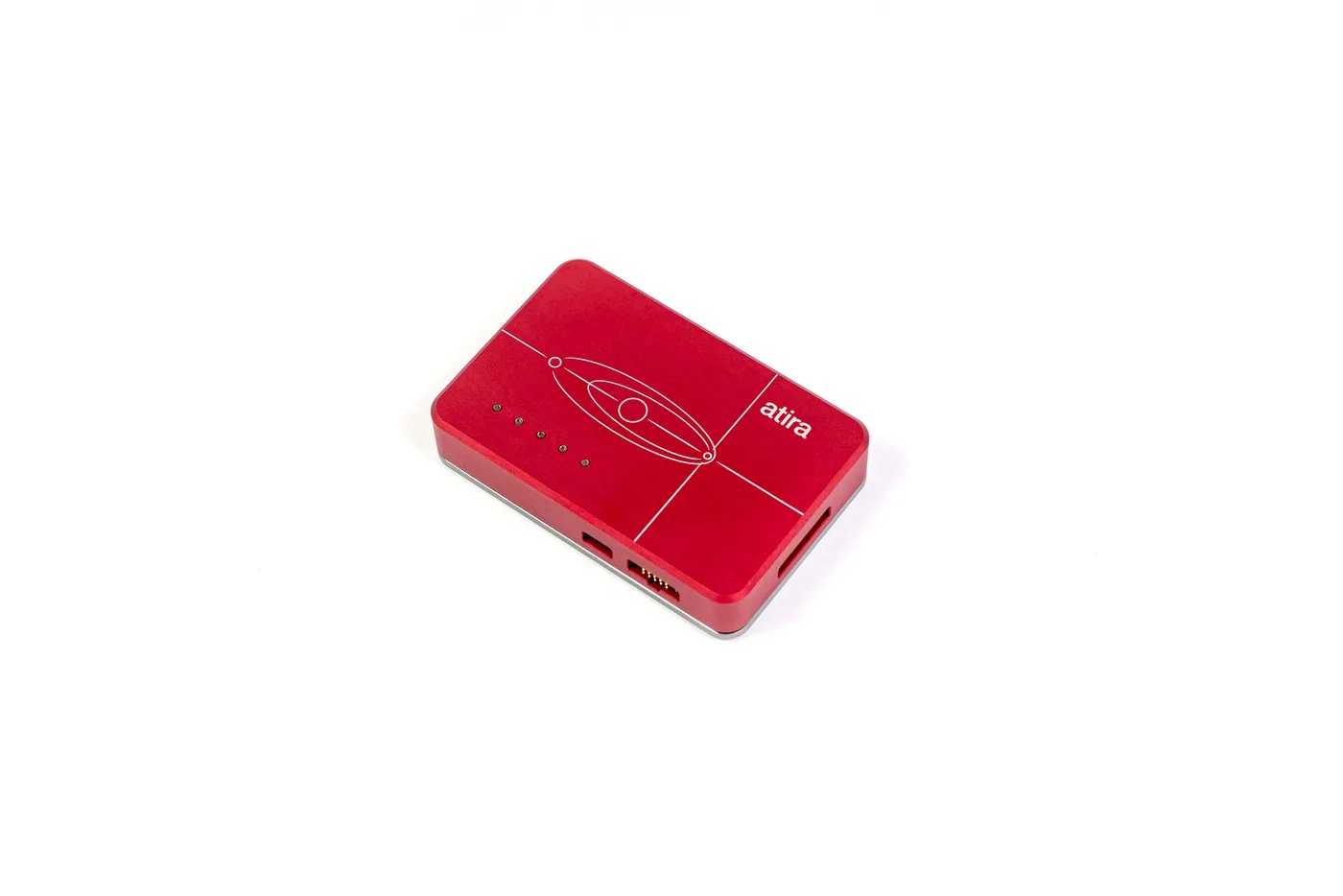
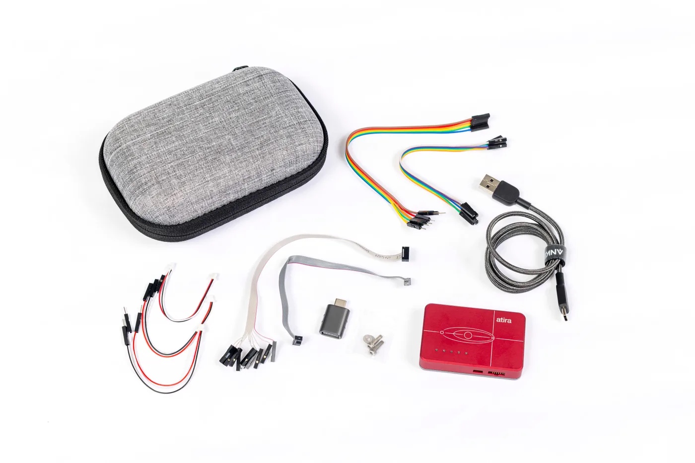
Binho Atira is a USB-C debug probe and programmer for embedded developers. It debugs Arm Cortex-M targets over SWD and JTAG, captures SWO trace and RTT, programs SPI flash and EEPROM, bridges the target’s serial console, and powers the board from a programmable 1.2 to 5.0 V supply while it measures voltage, current and power. On most bring-up benches, one aluminum box replaces the debug probe, the USB-to-serial cable and the bench supply.

Pertech is Binho’s authorized distributor in Israel. Atira is available to order now, and Binho begins shipping on November 9, 2026.

Highlights

  • Standard CMSIS-DAP v2 probe: works with pyOCD, OpenOCD and CMSIS-DAP-aware IDEs, with no vendor plug-in needed for core debug
  • SWD, JTAG, SWO trace and RTT, with RTT streaming while a debug session runs
  • SPI controller up to 24 MHz for SPI flash and EEPROM programming
  • USB-to-UART bridge up to 2 Mbaud with optional RTS/CTS, plus a second, read-only port to monitor the traffic
  • Programmable target supply from 1.2 to 5.0 V with live voltage, current and power readings
  • Level translation on every target-facing signal, 1.2 to 5.0 V
  • Power-cycles the target from software, without unplugging a cable
  • Binho Mission Control GUI, plus Python and C/C#/C++ SDKs, on Windows, macOS and Linux
  • Driverless USB and field-upgradeable firmware
  • Microchip PIC (ICSP) and AVR (UPDI) programming in development, with pre-release access from Binho

Where it earns its keep

  • Board bring-up. Power the board at the right voltage, watch its current, open the console and attach the debugger, all over one USB-C cable.
  • Firmware development and debug on Arm Cortex-M: breakpoints, stepping, memory and register access, flash programming.
  • Automated hardware and firmware testing. Script power cycles, flashing and console checks from Python or C, in CI rigs and agent-driven workflows.
  • SPI flash and EEPROM programming for firmware images and calibration data.
  • Production-line MCU programming. Run many Atira units from one PC as a gang programmer, and bolt each one into a fixture through its two M3 mounting holes.
  • Device driver development and proof-of-concept work, with the target’s serial output visible while you debug.

What’s in the box

Binho Atira with its programming, serial and UART cables, USB-C cable, adapter, mounting screws and zippered carry case

  • Binho Atira USB adapter
  • Programming port kit: 2×5 pin 1.27 mm IDC ribbon cable, and a second with 2.54 mm female headers
  • 6-pin serial port kit: cables with male and with female 2.54 mm headers
  • 3-pin UART kit: JST SH 1.0 mm cables with male headers and with a JST SH plug
  • USB Type-C to Type-A cable and USB Type-A to Type-C adapter
  • Mounting kit: 2 screws and 2 washers
  • Protective zippered carry case

Pairs well with

For hands-free probing, Binho recommends Sensepeek PCBite probes, which Pertech also supplies: see Sensepeek PCBite. For I2C, SPI, UART, RS-485 and I3C work beyond debug, see the Binho Pulsar host adapter and the Binho Supernova I3C adapter. All Binho products: Binho in Israel.

Key Specifications

SpecValue
ProductBinho Atira USB debug probe and programmer
SKUBIN109
Host interfaceUSB 2.0 Full-Speed (12 Mbps), USB Type-C, bus-powered, driverless (HID + CDC)
Debug standardCMSIS-DAP v2
Debug and traceSWD, JTAG (TCK, TMS, TDI, TDO, nTRST, nRESET), SWO, RTT
Supported debug targetsArm Cortex-M (SWD); devices with JTAG-DP or JTAG TAP
Microchip programmingICSP (PIC) and UPDI (AVR): in development, pre-release access from Binho
SPIController; modes 0 to 3; 10 kHz to 24 MHz; 8 or 16 bit; MSB or LSB first; up to 16 KB per transfer; 1 CS
UART600 baud to 2 Mbaud; 7 or 8 data bits; parity none, even or odd; 1 or 2 stop bits; optional RTS/CTS
Target I/O voltage1.2 to 5.0 V, level-shifted on every target-facing signal
Target supplyProgrammable 1.2 to 5.0 V in 1.1 mV steps; 500 mA recommended maximum per port; available current depends on the USB host port
Power monitoring16-bit; current 0 to 2.048 A (62.5 µA resolution); voltage up to 5.5 V (1.6 mV resolution)
Target ports2×5 pin 1.27 mm programming port; 6-pin 2.54 mm serial port; 3-pin JST SH 1.0 mm UART port
SoftwareBinho Mission Control GUI; Python (3.10+) and C/C#/C++ SDKs; Windows, macOS, Linux
EnclosureMachined aluminum, 5 RGB status LEDs, 2 M3 mounting holes, fanless
Operating temperature0 to 70 °C
ESD rating±4 kV
DatasheetBinho Atira datasheet, Rev 1.1 (PDF)

Frequently Asked Questions

What is Binho Atira?

Binho Atira is a USB-C debug probe and programmer from Binho. It debugs Arm Cortex-M targets over SWD and JTAG, captures SWO and RTT, programs SPI flash and EEPROM, bridges the target’s UART, and powers the target from a programmable 1.2 to 5.0 V supply with live voltage, current and power monitoring.

Which debug tools work with Binho Atira?

Atira is a standard CMSIS-DAP v2 probe, so it works with pyOCD, OpenOCD and IDEs that support CMSIS-DAP probes, with no vendor-specific plug-in for core debug. Arm Keil MDK supports CMSIS-DAP debug adapters; see Arm Keil MDK, and ask us to confirm your device.

Can Binho Atira power my board?

Yes. Atira can power the target from 1.2 to 5.0 V and measure its voltage, current and power continuously, or it can leave a self-powered target alone and match its I/O voltage. The current available depends on the USB host port. Atira’s monitoring is meant for functional checks and logging; for low-power or battery-life characterization, use a dedicated power analyzer.

Does Atira program Microchip PIC and AVR devices?

ICSP for PIC and UPDI for AVR are in active development. UPDI is planned for tinyAVR 0/1-series, AVR DA/DB and AVR DD/EA. Binho offers pre-release access; contact us and we will arrange it.

Can I use Binho Atira for production programming?

Yes. Many Atira units can run from one PC for gang programming and automated test stations, controlled from the Python or C/C#/C++ SDK. The aluminum enclosure has two M3 mounting holes, and the ports use standard off-the-shelf connectors for custom fixtures.

How is Atira different from Binho Pulsar and Supernova?

Atira is a debug probe and programmer for microcontrollers. Binho Pulsar is a multi-protocol USB host adapter for talking to I2C, SPI, UART and RS-485 devices. Binho Supernova is an I3C and I2C host adapter. Many teams use Atira for firmware and a host adapter for the peripherals around it.

Where can I buy Binho Atira in Israel?

From Pertech, Binho’s authorized distributor in Israel. We provide quotes in Israel, local delivery and technical support. Request a quote.

Need a quote, a demo or help choosing between Binho tools? Contact Pertech.

OBD2-to-DB9 Adapter Cable (Cars, Trucks, Buses)

OBD2 to DB9 Cable for CAN Loggers

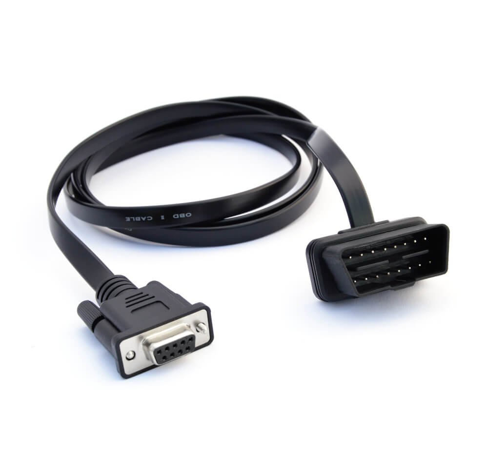
This OBD2 to DB9 cable is the quickest way to connect a logger or interface to a car. The quickest way onto a vehicle CAN bus is the OBD2 diagnostic socket, usually found under the dashboard near the steering wheel. This 1.5 m cable connects that socket to the standard DB9 port of a CANedge logger, CANsub interface or other CiA 303-1 device.

It uses a Type B OBD2 plug, whose split center pin fits both 12 V cars and 24 V vans and trucks. The flat connector head fits tight footwells, and the overmolded DB9 end stands up to daily use.

Highlights

  • OBD2 16-pin (Type B) to DB9 female
  • Fits 12 V cars and 24 V commercial vehicles
  • Powers a CANedge directly from the OBD2 socket (pin 16 to DB9 pin 9)
  • 1.5 m cable, 22 AWG
  • Flat plug head for tight spaces
  • Overmolded, RoHS-compliant cable
  • Works with the CANedge loggers, CANsub interfaces and CANmod modules, and any device with a CiA 303-1 DB9 port
OBD2-to-DB9 Adapter Cable (Cars, Trucks, Buses)

Pin-out

DB9 pinSignalVehicle side
2CAN-LOBD2 pin 14
3GNDOBD2 pin 4
7CAN-HOBD2 pin 6
9Power (VCC)OBD2 pin 16

DB9 pins follow CiA 303-1. Other pins are not connected.

Where it earns its keep

  • OBD2 data logging: record speed, RPM, fuel and other OBD2 PIDs from cars
  • Raw CAN access: log or stream the CAN traffic present on the diagnostic port
  • Fleet installations: plug-and-play connection without touching vehicle wiring
  • Development and diagnostics: connect a CANsub to a test vehicle in seconds

Key Specifications

SpecValue
ConnectorsOBD2 16-pin (Type B) to DB9 female
DB9 pin-outCiA 303-1 (CAN-L 2, GND 3, CAN-H 7, power 9)
Cable length1.5 m
Wire gauge22 AWG (0.5 mm²)
Vehicles12 V and 24 V (Type B)
Operating temperature-20 °C to +80 °C
Weight100 g
ComplianceRoHS

Frequently asked questions

Does it power the logger?

Yes. OBD2 pin 16 (battery power) is routed to DB9 pin 9, which powers a CANedge directly. Some vehicles cut this power when the ignition is off, others keep it on, so check the behavior on your vehicle. The CANsub is powered over USB or PoE instead.

Will it work on a truck?

Yes. The Type B plug fits 24 V vehicles. For heavy-duty vehicles with a 9-pin Deutsch diagnostic socket, use the J1939-to-DB9 cable instead.

Need a quote or help choosing the right setup? Contact Pertech, the CSS Electronics distributor in Israel.

J1939-to-DB9 Adapter Cable (Deutsch 9-Pin, Type 2)

J1939 to DB9 Cable (Deutsch 9-Pin)

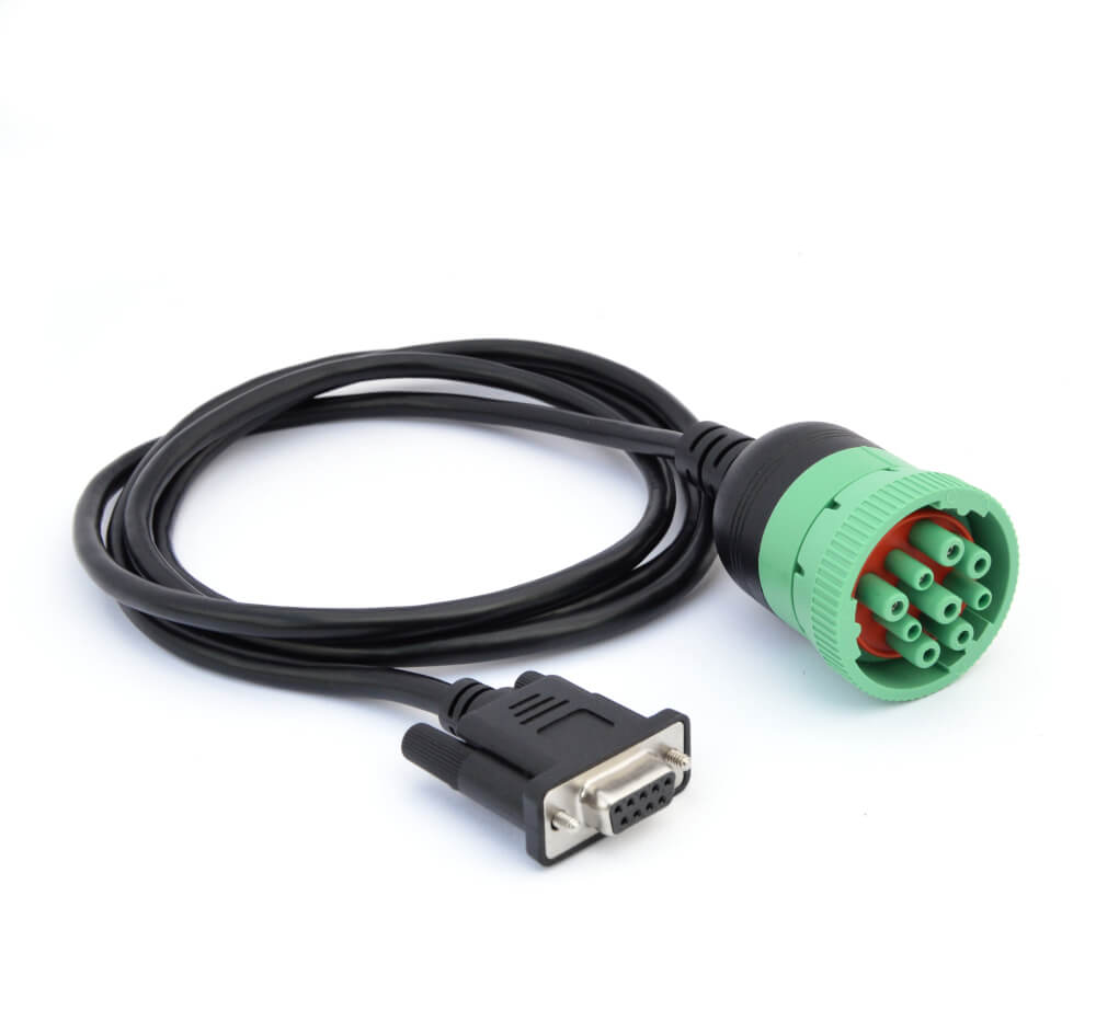
This J1939 to DB9 cable connects a logger or interface to most heavy-duty vehicles. Most trucks, buses and many tractors and construction machines have a 9-pin Deutsch J1939 diagnostic socket in the cab. This 1.5 m cable connects it to the DB9 port of a CANedge logger or CANsub interface, giving direct access to the J1939 network.

Unlike an OBD2 cable, it also carries vehicle power to the DB9 power pin, so a CANedge can run straight from the diagnostic socket with no extra wiring. The Type 2 connector fits both older and newer (green) J1939 sockets.

Highlights

  • J1939 Deutsch 9-pin (Type 2, female) to DB9 female
  • Supplies vehicle power to the logger via DB9 pin 9
  • 1.5 m cable, 22 AWG, overmolded ends
  • Works with CAN, CAN FD, J1939 and NMEA 2000 data
  • Works with the CANedge loggers, CANsub interfaces and CANmod modules, and any device with a CiA 303-1 DB9 port
J1939-to-DB9 Adapter Cable (Deutsch 9-Pin, Type 2)

Pin-out

DB9 pinSignalVehicle side
2CAN-LDeutsch pin D
3GNDDeutsch pin A
7CAN-HDeutsch pin C
9Power (VCC)Deutsch pin B

DB9 pins follow CiA 303-1. Other pins are not connected.

Where it earns its keep

  • Truck and bus telematics: install a CANedge on the diagnostic socket in minutes
  • Off-highway machines: log J1939 data from tractors, loaders and generators with a 9-pin socket
  • Diagnostics: connect a CANsub interface to read J1939 traffic and DM1 fault codes live
  • Fleet rollouts: one standard cable for most heavy-duty vehicles

Key Specifications

SpecValue
ConnectorsJ1939 Deutsch 9-pin (Type 2, female) to DB9 female
DB9 pin-outCiA 303-1 (CAN-L 2, GND 3, CAN-H 7, power 9)
Cable length1.5 m
Wire gauge22 AWG (0.5 mm²)
CompatibilityHigh-speed CAN (ISO 11898-2), CAN FD, J1939, NMEA 2000
Operating temperature-20 °C to +80 °C
Weight180 g

Frequently asked questions

Does it power the logger?

Yes. Vehicle power from Deutsch pin B is routed to DB9 pin 9, which powers a CANedge directly. The CANsub is powered over USB or PoE instead.

What does Type 2 mean?

Type 2 (Type II) connectors fit both the older black 250 kbit/s sockets and the newer green 500 kbit/s J1939 sockets.

What if my vehicle has a different connector?

CSS Electronics offers DB9 adapters for many others, such as OBD2, Caterpillar, Volvo Penta and RP1226. Contact us with a photo of the socket and we will find the right cable.

Need a quote or help choosing the right setup? Contact Pertech, the CSS Electronics distributor in Israel.

CANCrocodile (CH2): Contactless CAN Bus Reader

CANCrocodile: Contactless CAN Reader for the Wiring Harness

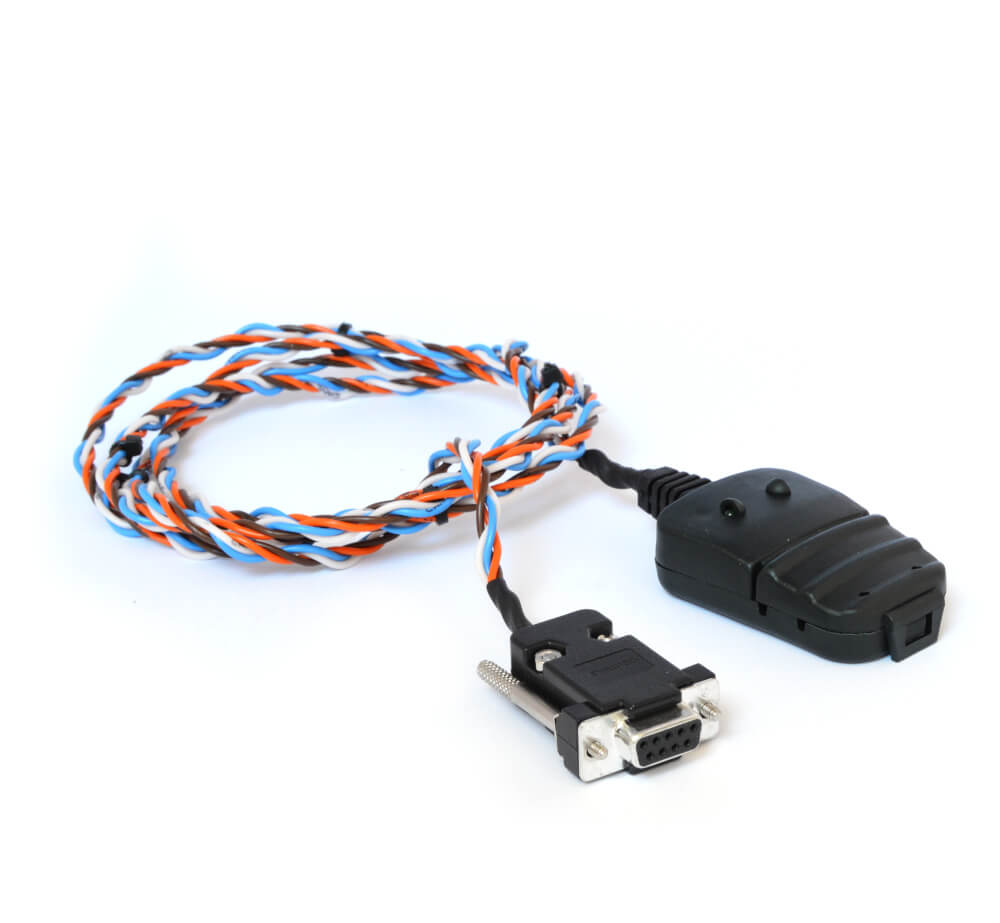
The CANCrocodile is a contactless CAN reader. Sometimes the data you need is not on the diagnostic connector, or the vehicle owner will not accept cut or pierced wires. The CANCrocodile clamps around the CAN-High and CAN-Low wires and picks up the signal through their electromagnetic field, with no electrical contact at all.

This version plugs into the second port of a CANedge logger and takes its 5 V supply from there. Clip it on, power up the logger, and CAN frames from that harness are recorded like any other channel, while the vehicle wiring and its warranty stay untouched.

Highlights

  • Contactless pickup: no cutting, splicing or piercing
  • Clamps directly on the CAN-H / CAN-L wire pair anywhere in the harness
  • Powered from the CANedge second port (5 V)
  • High-speed CAN, 5 kbit/s to 1 Mbit/s
  • Internally terminated; LEDs for power and data
  • Firm perpendicular grip so the wires do not slip
CANCrocodile (CH2): Contactless CAN Bus Reader

Where it earns its keep

  • OEM and leased vehicles: log data without affecting the warranty or leaving traces
  • Buses that are not on the OBD2 or J1939 port: reach internal networks behind gateways
  • Fleet telematics: fast, non-invasive installation across many vehicles
  • Agriculture and machinery: tap J1939 harnesses on equipment without a diagnostic connector
Designed for the second CAN port of the CANedge series. The CAN wires must be accessible as a twisted pair in the harness.

Key Specifications

SpecValue
FunctionContactless (inductive) CAN bus reader
CompatibilityHigh-speed CAN (ISO 11898-2): J1939, OBD2, NMEA 2000, CANopen and more
Bit rates5 kbit/s to 1 Mbit/s
Supply5 V from CANedge second-port power output
ConnectorDB9 female, CiA 303-1 pinout (for CANedge CH2)
Cable length70 cm
TerminationInternal 120 Ω
LEDsRed: power; green: CAN data detected
Operating temperature-20 °C to +80 °C
IP ratingIP30
Weight100 g

Frequently asked questions

Does the CANCrocodile affect the vehicle?

No. It reads the electromagnetic field around the wires without any electrical connection, so nothing is cut, pierced or loaded, and the vehicle wiring stays as it was.

Which logger does it work with?

This CH2 version is made for the second port of the CANedge1, CANedge2 and CANedge3, which supplies its 5 V power.

Can it transmit on the bus?

No. It is a receive-only, contactless reader, which is exactly what makes it safe for non-invasive logging.

Need a quote or help choosing the right setup? Contact Pertech, the CSS Electronics distributor in Israel.

NMEA 2000 DBC File + License: Decode Marine Data

NMEA 2000 DBC File: Decode Data from Boats and Ships

NMEA 2000 is the CAN-based network that connects engines, GPS receivers, wind and depth sensors, batteries and displays on boats and ships. The NMEA 2000 DBC file decodes its standard messages into readable values such as speed through water, wind angle, engine temperature or battery state.

It is built on the official NMEA 2000 PGN database, version 3.000 (2022), and the bundle includes the NMEA 2000 Appendix A and B documents themselves, which also gives you the license to use them. If you already own the appendices, a lower-priced version without them is available against proof of purchase.

Highlights

  • 170+ NMEA 2000 PGNs and about 1500 signals
  • Single-frame and fast-packet messages
  • Value tables included where meaningful
  • Includes NMEA 2000 Appendix A and B (v3.000, 2022) with license
  • IDs matched on the 18-bit PGN, so it works across source addresses
  • Works in any CAN tool that imports DBC files, including the CANedge and CANsub software and the free asammdf GUI
NMEA 2000 DBC File + License: Decode Marine Data

Where it earns its keep

  • Vessel monitoring: log engine, fuel, battery and navigation data on yachts and work boats
  • Marine equipment development: test NMEA 2000 devices against real network traffic
  • Fleet operations: track usage and performance across boats with a CANedge2 or CANedge3
  • Research vessels: combine environmental and navigation data on one timeline

Key Specifications

SpecValue
ProductNMEA 2000 DBC file (CSS Electronics)
SKUS012
SourceNMEA 2000 PGN database v3.000 (2022), Appendix A and B included
PGNs170+
SignalsAbout 1500 (of about 1800 in the database)
Message typesSingle-frame and fast-packet PGNs
ID matchingVFrameFormat J1939PG (matched on 18-bit PGN)
Value tablesIncluded where meaningful
VersionsIncluding Appendix A and B, or excluding them (proof of purchase required)
DeliveryDigital download

Frequently asked questions

Why is the NMEA 2000 appendix included?

The NMEA 2000 PGN definitions are licensed by the NMEA. Including Appendix A and B in the bundle gives you that license with the DBC, so no separate purchase is needed. Owners of the appendices can buy the version without them.

How much of my vessel data will it decode?

Most standard NMEA 2000 data on a typical vessel, with the remainder being manufacturer-specific messages. The DBC covers about 1500 of the roughly 1800 signals in the NMEA database; the rest cannot be represented in DBC format.

Can I test it before buying?

Yes. Send us a sample CANedge log from the vessel and we will help arrange a free sample decoding with CSS Electronics.

Need a quote or help choosing the right setup? Contact Pertech, the CSS Electronics distributor in Israel.

ISOBUS DBC File: Decode Tractor and Implement Data (ISO 11783)

ISOBUS DBC File: Turn Tractor CAN Data into Agronomic Values

ISOBUS (ISO 11783) is the shared language of tractors and implements across brands. The ISOBUS DBC file decodes its standard messages into physical values such as ground speed, distance, hitch position and power take-off data, ready for analysis in any DBC-capable tool.
The package also includes a separate process-data DBC covering 750+ implement data dictionary identifiers (DDIs): application rates, seed rates, worked area and similar values exchanged between tractor and implement. It is a one-time purchase.

Highlights

  • About 100 PGNs and 650+ SPNs from ISO 11783-7
  • Separate process-data DBC with 750+ DDIs from ISO 11783-11
  • Excel reference file with full descriptions and value lookups
  • One-time fee, no per-user license tiers
  • Works in any CAN tool that imports DBC files, including the CANedge and CANsub software and the free asammdf GUI
  • Combines with the J1939 and NMEA 2000 DBC files used on the same machines
ISOBUS DBC File: Decode Tractor and Implement Data (ISO 11783)

Where it earns its keep

  • Precision agriculture: log application rates, seed rates and worked area per field
  • Machine development: validate tractor-implement communication during testing
  • Fleet and contractor operations: track machine usage across farms and seasons
  • Research: collect field data from mixed-brand equipment through one standard
Many tractors use J1939, ISOBUS and NMEA 2000 side by side: J1939 for the engine, ISOBUS for ground speed and implement data, NMEA 2000 for some navigation equipment. Combining the matching DBC files gives the fullest picture.

Key Specifications

SpecValue
ProductISOBUS DBC file (CSS Electronics)
SKUS008
StandardsISO 11783-7 and ISO 11783-11
PGNsAbout 100
SPNs650+
Process data (DDIs)750+, in a separate multiplexed DBC
DescriptionsPartial in the DBC, full in the Excel file
Signal attributesSPN ID, VFrameFormat
Value tablesNot included (see Excel file)
Included filesISOBUS DBC, process-data DBC, Excel reference file
LicenseOne-time fee
DeliveryDigital download

Frequently asked questions

How much of a tractor will the ISOBUS DBC decode?

It decodes the standardized ISOBUS parameters. Manufacturers also send proprietary data that no public database covers. CSS Electronics reports typical coverage of 60 to 80 percent of the ISOBUS signals on a tractor.

Do I also need the J1939 DBC?

Often yes. Engine and powertrain data on tractors is usually J1939, while ISOBUS carries ground speed, distance and implement data. Using both DBC files covers the most signals.

Can I test it before buying?

Yes. Send us a sample CANedge log or a CANsub CSV export and we will help arrange a free sample decoding with CSS Electronics.

Need a quote or help choosing the right setup? Contact Pertech, the CSS Electronics distributor in Israel.
J1939-73 DBC File: Heavy-Duty Diagnostics (DM1, DM2 and more)

J1939-73 DBC File: Read Fault Codes from Heavy-Duty Vehicles

When a truck, bus or tractor reports a problem, it does so through J1939-73 diagnostic messages: DM1 for active faults, DM2 for previously active ones, and dozens more. The J1939-73 DBC file decodes these messages into readable fields, so a log shows exactly which component failed, how, and how often.
It complements the J1939 DBC file: that one decodes operating signals such as speed, RPM and temperatures, while this one decodes diagnostics. Both are produced by CSS Electronics in collaboration with SAE and come with a legal license.

Highlights

  • 50+ diagnostic messages (DM1, DM2 and more) split into signals
  • 2000+ SPNs referenced in fault codes
  • DTCs split into SPN, failure mode (FMI), occurrence count and conversion method
  • Includes the SAE J1939-73 (2022-08) standard as PDF, with license
  • Works in any CAN tool that imports DBC files, including the CANedge and CANsub software and the free asammdf GUI
  • Saves the time and risk of building a diagnostics DBC by hand
J1939-73 DBC File: Heavy-Duty Diagnostics (DM1, DM2 and more)

Where it earns its keep

  • Fleet maintenance: log active and stored fault codes across vehicles and spot issues early
  • Warranty and failure analysis: see which faults occurred, when and how often
  • Field testing: catch DTCs raised during prototype and validation runs
  • Remote diagnostics: combine with a CANedge2 or CANedge3 to receive fault data over WiFi or 4G
Decoding J1939-73 data needs a tool that handles the J1939 transport protocol, because many diagnostic messages span several CAN frames. The CANedge software and asammdf support this.

Key Specifications

SpecValue
ProductSAE J1939-73 DBC file (CSS Electronics, in collaboration with SAE)
SKUS009
Source standardSAE J1939-73 (2022-08), PDF included
Diagnostic messages50+
SPNs2000+
DTC fieldsSPN, SPN high bits, FMI, occurrence count, conversion method
DTC encodingVersion 4 encoding (CM = 0) only
MultipacketMultipacket syntax for multipacket PGNs
DescriptionsPartial in the DBC, full in the PDF
Value tablesSome included
License1 user, 1 PC (2- and 5-user packs available)
DeliveryDigital download

Frequently asked questions

Do I need the J1939-73 DBC or the J1939 DBC?

For operating data such as speed, RPM and temperatures, the J1939 DBC is enough. Add the J1939-73 DBC when you also need to read and analyze diagnostic trouble codes. Many fleet and testing projects use both.

Which tools can decode it?

A tool that supports the J1939 transport protocol, since diagnostic messages often span several frames. The CANedge software and the free asammdf GUI handle this, as do professional J1939 diagnostic tools.

Can I test it before buying?

Yes. If you log with a CANedge, send us a sample log and we will help arrange a free sample decoding with CSS Electronics before you order.

Need a quote or help choosing the right setup? Contact Pertech, the CSS Electronics distributor in Israel.

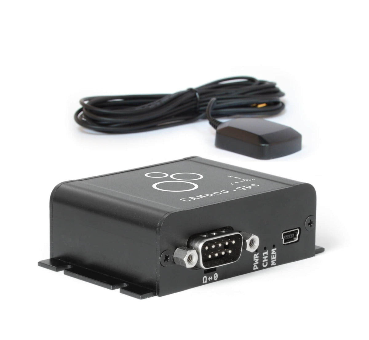
CANmod.gps: GNSS + IMU to CAN Module

CANmod.gps: GPS to CAN Module with Motion Data

The CANmod.gps is a GPS to CAN module with a built-in inertial sensor. Location, speed, heading and acceleration add context to any vehicle log: where a fault happened, how hard the brakes were applied, which route a machine took. The CANmod.gps produces all of it and sends it as CAN messages, so any logger or ECU on the bus can use it.

It is built around a u-blox NEO-M8U receiver with a built-in gyroscope and accelerometer. In vehicles, sensor fusion (untethered dead reckoning) keeps the position accurate through tunnels, parking garages and urban canyons where satellite reception drops.

Highlights

  • u-blox NEO-M8U GNSS with 3D gyroscope and accelerometer
  • GPS, Galileo, BeiDou and GLONASS
  • Dead reckoning (UDR) for vehicles: positioning through signal loss
  • 2.5 m CEP position accuracy; 1 s reacquisition
  • Up to 4 configurable geofences, reported via CAN
  • GPS antenna included; DBC file for decoding included
CANmod.gps: GNSS + IMU to CAN Module

Where it earns its keep

  • Vehicle and fleet logging: add position, speed and route to CANedge J1939 or OBD2 logs
  • Driving dynamics: capture acceleration, rotation and heading during tests
  • Machines and agriculture: record where and how equipment operates
  • Geofencing: trigger events when a vehicle enters or leaves an area

Key Specifications

SpecValue
FunctionOutputs GNSS position and IMU motion data on CAN (or USB)
Receiveru-blox NEO-M8U, 72 channels, built-in gyroscope and accelerometer
ConstellationsGPS, Galileo, BeiDou, GLONASS (and combinations)
Sensor fusionUntethered dead reckoning (UDR) of GNSS and IMU, for automotive use
Accuracy2.5 m CEP (position)
Time to fixCold start 26 s, aided start 3 s, reacquisition 1 s
SensitivityTracking -160 dBm, cold start -148 dBm, hot start -157 dBm
Geofences0-4 circular geofences, status via CAN
CAN output1 x CAN up to 1 Mbit/s; configurable IDs (11/29-bit), push or poll, message rates
ConnectorDB9 (CAN and power)
AntennaGPS antenna included (SMA, 3 m cable, magnetic base)
EnclosureAluminium, 65 x 48 x 24 mm, 70 g, 4 LEDs
Power+5 to +26 V DC via the DB9 connector (pin 1 or 9); under 1 W
ConfigurationJSON configuration files (same concept as the CANedge), via USB
USBMini USB for configuration, firmware updates and live streaming
Operating temperature-25 °C to +70 °C
IP ratingIP40
Made inDenmark

Frequently asked questions

Do I need the CANmod.gps if my CANedge already has GPS?

The CANedge1, CANedge2 and CANedge3 variants with GNSS/IMU have position data built in. The CANmod.gps is for loggers or systems without it, such as other CAN loggers, ECUs or interfaces, or when you need the data shared on the CAN bus itself.

Does a CANmod need a PC or a logger to work?

No. Once configured, it runs on its own from the DB9 power pins and puts its data straight onto the CAN bus. A PC is only needed over USB to change the configuration, update firmware or watch the data live.

How do I decode the CAN messages it sends?

CSS Electronics provides a DBC file describing every message and signal the module outputs, so any DBC-capable tool, including the CANedge software and asammdf, shows the values directly in engineering units.

Need a quote or help choosing the right setup? Contact Pertech, the CSS Electronics distributor in Israel.

CANmod.input: 8 x Analog / Digital / Pulse to CAN Converter

CANmod.input: Analog to CAN Converter for Any Sensor

The CANmod.input is an analog to CAN converter for up to eight sensors. Not every measurement you need is already on the vehicle network. The CANmod.input reads up to eight external sensors, such as pressure transducers, potentiometers, switches, flow meters or wheel-speed pickups, and publishes their values as CAN messages.

Every channel is sampled three ways at once: as an analog voltage, as a digital on/off state and as a pulse frequency or counter. Your logger or ECU sees the sensor data next to the regular CAN traffic, with a ready DBC file to decode it.

Highlights

  • 8 input channels, each read as analog, digital and pulse
  • Configurable ranges from 0-0.625 V to 0-10 V, 10-bit
  • 1 kHz analog and digital sampling, 16 kHz pulse sampling
  • Pulse inputs as frequency or 32-bit counter
  • 3.3 V excitation supply for each sensor
  • Runs standalone; DBC file for decoding included
CANmod.input: 8 x Analog / Digital / Pulse to CAN Converter

Where it earns its keep

  • Vehicle testing: add brake pressure, pedal position or suspension travel sensors to a CAN log
  • Machinery and agriculture: capture hydraulic pressures, switches and shaft speeds alongside J1939 data
  • Test rigs: bring lab sensors onto the same timeline as ECU traffic
  • Retrofit monitoring: instrument older equipment that has no sensor bus of its own

Key Specifications

SpecValue
FunctionReads 8 sensors and outputs the values on CAN (or USB)
Input channels8, each sampled as analog, digital and pulse
Analog ranges0-10 V, 0-5 V, 0-2.5 V, 0-1.25 V, 0-0.625 V; 10-bit
SamplingAnalog and digital 1 kHz; pulse 16 kHz
Digital inputsConfigurable high/low thresholds with hysteresis
Pulse inputsFrequency or counter mode, up to 32 bit
Input impedance136 kΩ; over- and undervoltage protected
Sensor supplyAbout 3.3 V excitation per channel, 100 mA shared
CAN output1 x CAN, classic CAN 5 kbit/s to 1 Mbit/s or CAN FD (1, 2, 4 Mbit/s); broadcast or on request
ConnectorsDB9 (CAN and power), DB25 (sensors); DB25 sensor adapters available
EnclosureAluminium, 65 x 48 x 24 mm, 70 g, 8 LEDs
Power+5 to +26 V DC via the DB9 connector (pin 1 or 9); under 1 W
ConfigurationJSON configuration files (same concept as the CANedge), via USB
USBMini USB for configuration, firmware updates and live streaming
Operating temperature-25 °C to +70 °C
IP ratingIP40
Made inDenmark

Frequently asked questions

What kinds of sensors can I connect?

Any sensor with a voltage output up to 10 V, any switch or digital signal, and any pulse output such as a hall-effect speed sensor or flow meter. Each channel delivers analog, digital and pulse readings at the same time, so you choose in software which values to use.

Does a CANmod need a PC or a logger to work?

No. Once configured, it runs on its own from the DB9 power pins and puts its data straight onto the CAN bus. A PC is only needed over USB to change the configuration, update firmware or watch the data live.

How do I decode the CAN messages it sends?

CSS Electronics provides a DBC file describing every message and signal the module outputs, so any DBC-capable tool, including the CANedge software and asammdf, shows the values directly in engineering units.

Need a quote or help choosing the right setup? Contact Pertech, the CSS Electronics distributor in Israel.

CANmod.temp: 4 x Thermocouple to CAN Converter

CANmod.temp: Thermocouple to CAN Module

The CANmod.temp is a thermocouple to CAN module with four channels. Temperatures that the vehicle does not report itself, such as exhaust, brake, battery cell or coolant line, are often exactly what a test needs. The CANmod.temp reads up to four thermocouples and sends calibrated temperatures in degrees Celsius over CAN.

It handles cold-junction compensation and linearization internally, flags broken or out-of-range probes, and works with all common thermocouple types. Connect it to a CANedge and the temperatures are logged on the same timeline as the rest of the bus.

Highlights

  • 4 thermocouple channels plus ambient (cold-junction) temperature
  • Thermocouple types B, E, J, K, N, R, S and T
  • -210 °C to +1800 °C, depending on probe type
  • Output in °C at 1 °C or 0.01 °C resolution
  • Open-probe and over/under-temperature fault reporting
  • 50/60 Hz line-noise filtering; DBC file included
CANmod.temp: 4 x Thermocouple to CAN Converter

Where it earns its keep

  • Exhaust and aftertreatment testing: log EGT and catalyst temperatures alongside engine data
  • Brakes and drivetrain: monitor disc, gearbox and bearing temperatures during validation
  • EV batteries: add independent temperature points to battery pack tests
  • Industrial equipment: track process and motor temperatures on machines with a CAN network
When measuring on conductive surfaces such as metal parts, use isolated (insulated-junction) thermocouple probes. A set of four type K probes is available as an accessory.

Key Specifications

SpecValue
FunctionReads 4 thermocouples and outputs temperatures on CAN (or USB)
Channels4 thermocouples plus cold-junction (ambient) temperature
ConverterMAX31856 precision thermocouple converter
Thermocouple typesB, E, J, K, N, R, S, T (configurable per channel)
Range-210 °C to +1800 °C, depending on type
Resolution1 °C (one CAN frame) or 0.01 °C (two CAN frames)
Cold-junction accuracy±0.7 °C max (-20 °C to +85 °C)
Fault detectionOpen thermocouple, over- and undertemperature, reported via CAN
Noise filtering50 Hz or 60 Hz line-frequency rejection
CAN output1 x CAN, 5 kbit/s to 1 Mbit/s; broadcast or on request; configurable IDs and rates
ConnectorsDB9 (CAN and power), 4 x miniature thermocouple sockets
EnclosureAluminium, 65 x 48 x 24 mm, 80 g, 3 LEDs
Power+5 to +26 V DC via the DB9 connector (pin 1 or 9); under 1 W
ConfigurationJSON configuration files (same concept as the CANedge), via USB
USBMini USB for configuration, firmware updates and live streaming
Operating temperature-25 °C to +70 °C
IP ratingIP40
Made inDenmark

Frequently asked questions

Which thermocouple probes can I use?

Any type B, E, J, K, N, R, S or T probe with a miniature thermocouple plug. Type K is the most common general-purpose choice. On metal surfaces, use isolated probes.

Does a CANmod need a PC or a logger to work?

No. Once configured, it runs on its own from the DB9 power pins and puts its data straight onto the CAN bus. A PC is only needed over USB to change the configuration, update firmware or watch the data live.

How do I decode the CAN messages it sends?

CSS Electronics provides a DBC file describing every message and signal the module outputs, so any DBC-capable tool, including the CANedge software and asammdf, shows the values directly in engineering units.

Need a quote or help choosing the right setup? Contact Pertech, the CSS Electronics distributor in Israel.

CANmod.router: 4 x CAN FD to 1 x CAN (or USB) Gateway

CANmod.router: Bring Four CAN FD Buses onto One

Modern vehicles and machines rarely have just one CAN bus. The CANmod.router collects traffic from up to four isolated CAN or CAN FD networks and delivers it over a single CAN bus or a USB link, with no configuration needed to get started.

Pair it with a CANedge logger in mux mode and a two-channel logger records five buses: the free software splits the data back into its original channels afterwards. Used on its own, it works as a compact gateway that merges, filters or forwards traffic between networks.

Highlights

  • 4 x CAN FD inputs with galvanic isolation, 1 x CAN FD output
  • Output over CAN or USB
  • Mux mode: log five CAN buses with one CANedge
  • Gateway mode: merge, split and filter traffic between buses
  • Silent (listen-only) mode and 32 ID filters per channel
  • Small aluminium housing, 75 g, 7 status LEDs
CANmod.router: 4 x CAN FD to 1 x CAN (or USB) Gateway

Where it earns its keep

  • Multi-bus vehicle logging: record powertrain, chassis, body and diagnostic buses from one logger
  • CAN gateways: forward selected messages between networks, or protect one bus from another
  • Test benches: bring several ECUs onto a single interface for analysis
  • Retrofit telematics: add bus coverage to an existing installation without new wiring to the cab

Key Specifications

SpecValue
FunctionRoutes 4 isolated CAN / CAN FD buses to 1 CAN / CAN FD bus or USB
Secondary channels4 x CAN FD, basic galvanic isolation
Primary channel1 x CAN FD (switchable termination)
CAN standardISO 11898; classic CAN 5 kbit/s to 1 Mbit/s; CAN FD 1, 2, 4, 5 Mbit/s; 11 and 29-bit IDs
ModesMux mode (tunnelled via primary bus, for CANedge) and gateway mode
Filtering32 ID filters per channel (mask, acceptance, rejection), prescaling
Silent modeRestricted (acknowledge only) or monitoring (no transmission)
Bus protection±25 kV HBM ESD, ±12 kV IEC ESD, ±14 V bus fault, short circuit
ConnectorsDB9 (primary bus and power), DB25 (4 secondary buses; DB25 to 4 x DB9 adapter available)
EnclosureAluminium, 65 x 48 x 24 mm, 75 g, 7 LEDs
Power+5 to +26 V DC via the DB9 connector (pin 1 or 9); under 1 W
ConfigurationJSON configuration files (same concept as the CANedge), via USB
USBMini USB for configuration, firmware updates and live streaming
Operating temperature-25 °C to +70 °C
IP ratingIP40
Made inDenmark

Frequently asked questions

How can a two-channel CANedge log five CAN buses with the CANmod.router?

In mux mode the router packs the traffic of its four secondary buses into tunnelled frames on its primary bus. The CANedge logs that bus plus its own second channel, and the free CSS software unpacks the tunnelled data back into the original channels and timestamps.

Does a CANmod need a PC or a logger to work?

No. Once configured, it runs on its own from the DB9 power pins and puts its data straight onto the CAN bus. A PC is only needed over USB to change the configuration, update firmware or watch the data live.

Which connector adapters do I need?

The four secondary buses share a DB25 connector. Most setups add the DB25 to 4 x DB9 adapter, then standard DB9 cables such as OBD2-to-DB9 or J1939-to-DB9 for each bus.

Need a quote or help choosing the right setup? Contact Pertech, the CSS Electronics distributor in Israel.

CANsub.4: 4 x CAN FD Interface (USB + Ethernet)

CANsub.4: Four-Channel CAN FD Interface over USB and Ethernet

The CANsub.4 gives one PC, server or test script live access to four CAN or CAN FD networks at once, in a palm-sized aluminium box. It is built for gateways, vehicles and machines with several buses, and for test benches where you want to watch every network side by side.

It works over USB for a laptop on the desk, or over Ethernet as a shared network device. The webCAN app runs on the interface, so a browser is all you need to stream, decode with a DBC and plot. For automation it supports python-can, SocketCAN and open REST and WebSocket APIs.

Highlights

  • 4 x CAN FD channels, galvanically isolated
  • USB-C and Ethernet in one compact aluminium unit
  • Browser-based webCAN app runs on the device: zero install
  • 20,000+ frames/s with 1 µs hardware timestamps
  • Optional PTP time sync for multi-device setups
  • python-can, SocketCAN, SavvyCAN, PlotJuggler and open APIs
  • Encrypted connections (TLS) with optional mTLS access control
CANsub.4: 4 x CAN FD Interface (USB + Ethernet)

One connector, four buses

All four channels share a single DB25 connector. An optional DB25 to 4 x DB9 adapter splits them into standard DB9 ports for OBD2 and J1939 adapter cables.

Where it earns its keep

  • Vehicle and machine development: watch and inject traffic on CAN and CAN FD networks during prototyping and validation
  • Multi-bus gateways: monitor powertrain, chassis and body networks of the same vehicle together, with aligned timestamps
  • Remote and test-bench access: put the interface on the network over Ethernet, or behind a WiFi or LTE router, and reach it from anywhere on the LAN
  • Automation and HIL: drive it from Python, SocketCAN or the REST/WebSocket APIs inside test scripts and CI rigs
  • Reverse engineering and DBC work: stream raw frames, decode them with a DBC and plot signals live in the browser

Key Specifications

SpecValue
FunctionCAN / CAN FD to USB and Ethernet interface, 4 channels
CAN channels4 x CAN FD, basic galvanic isolation
CAN standardISO 11898; CAN 2.0A/2.0B (11 and 29-bit IDs)
Bit ratesClassic CAN 5 kbit/s to 1 Mbit/s; CAN FD data phase 1, 2, 4, 5 Mbit/s; auto-detect or custom bit timing
Throughput20,000+ frames/s across all channels
Timestamps1 µs hardware timestamps on RX and TX; optional PTP sync (about 10 µs across devices)
Other CAN featuresSilent mode, hardware ID filters, error frames, RTR frames, custom frame transmit
Host interfacesUSB-C and RJ45 Ethernet
SecurityTLS 1.2 encryption, optional mutual TLS (mTLS), mDNS discovery
SoftwarewebCAN (on device), python-can, SocketCAN, SavvyCAN, PlotJuggler, REST and WebSocket APIs
DisplayColor TFT, 160 x 80 px: device URL, channel status, bit rate, bus load, errors
CAN connector1 x DB25 (D-sub 25); optional DB25 to 4 x DB9 adapter
Power+5 V via USB-C (Power-over-Ethernet adapter available); under 1 W
EnclosureAluminium, 75 x 67 x 20 mm, 90 g, IP40, M3 mounting flanges
Operating temperature-25 °C to +70 °C
CertificationsCE, FCC, IC, RoHS
Security updatesMinimum 5 years from purchase (EU Cyber Resilience Act)
Warranty1 year
Made inDenmark

Frequently asked questions

Do I need to install software to use the CANsub?

No. The webCAN app runs on the device itself. Connect it, type the URL shown on its display into a browser, and you can configure it, send and receive frames, decode with a DBC file and plot signals. For scripting, it also supports python-can, SocketCAN, SavvyCAN, PlotJuggler and open REST and WebSocket APIs.

Should I connect over USB or Ethernet?

USB is the quickest option for a laptop on the desk or a short in-vehicle session, and it also powers the device. Ethernet suits permanent installations, test benches shared by a team and remote sites, and works through WiFi or cellular routers. Traffic is encrypted with TLS, with optional mutual TLS authentication.

Which CAN protocols does it handle?

Any protocol that runs on classic CAN or CAN FD, including J1939, CANopen, NMEA 2000, OBD2, UDS and CCP/XCP. Bit rates from 5 kbit/s to 1 Mbit/s are supported for classic CAN and 1, 2, 4 and 5 Mbit/s for the CAN FD data phase, with automatic bit-rate detection.

How does the CANsub relate to the CANedge loggers?

They complement each other. The CANedge records data on its own for days or months; the CANsub is a live interface for when a person or a script needs to see and send traffic in real time. Both use the same DBC files and much of the same software ecosystem.

What is the difference between the CANsub.4 and CANsub.2?

Only the channel count and the connector. The CANsub.4 has four CAN FD channels on one DB25 connector; the CANsub.2 has two channels on two DB9 connectors. Software, timing and interfaces are the same.

Need a quote or help choosing the right setup? Contact Pertech, the CSS Electronics distributor in Israel.

CANsub.2: 2 x CAN FD Interface (USB + Ethernet)

CANsub.2: Dual CAN FD Interface over USB and Ethernet

The CANsub.2 connects a PC, a server or a test script to two CAN or CAN FD networks at once. Plug it in over USB and it works as a classic desk-side interface; connect it over Ethernet and it becomes a network device that a whole team, or a remote rig, can reach.

There is nothing to install. The webCAN app runs on the interface itself: type the address shown on its small display into a browser, and you can send and receive frames, decode signals with a DBC file and plot them live. Developers get python-can, SocketCAN and open REST and WebSocket APIs on the same hardware.

Highlights

  • 2 x CAN FD channels, galvanically isolated
  • USB-C and Ethernet in one compact aluminium unit
  • Browser-based webCAN app runs on the device: zero install
  • 20,000+ frames/s with 1 µs hardware timestamps
  • python-can, SocketCAN, SavvyCAN, PlotJuggler and open APIs
  • Encrypted connections (TLS) with optional mTLS access control
  • Built-in display with live channel status and device address
CANsub.2: 2 x CAN FD Interface (USB + Ethernet)

Two standard DB9 ports

Each channel has its own DB9 connector, so the CANsub.2 works directly with standard OBD2-to-DB9 and J1939-to-DB9 adapter cables.

Where it earns its keep

  • Vehicle and machine development: watch and inject traffic on CAN and CAN FD networks during prototyping and validation
  • Field diagnostics: plug into a truck, tractor or test rig with a laptop over USB and start streaming in seconds
  • Remote and test-bench access: put the interface on the network over Ethernet, or behind a WiFi or LTE router, and reach it from anywhere on the LAN
  • Automation and HIL: drive it from Python, SocketCAN or the REST/WebSocket APIs inside test scripts and CI rigs
  • Reverse engineering and DBC work: stream raw frames, decode them with a DBC and plot signals live in the browser

Key Specifications

SpecValue
FunctionCAN / CAN FD to USB and Ethernet interface, 2 channels
CAN channels2 x CAN FD, basic galvanic isolation
CAN standardISO 11898; CAN 2.0A/2.0B (11 and 29-bit IDs)
Bit ratesClassic CAN 5 kbit/s to 1 Mbit/s; CAN FD data phase 1, 2, 4, 5 Mbit/s; auto-detect or custom bit timing
Throughput20,000+ frames/s across all channels
Timestamps1 µs hardware timestamps on RX and TX; optional PTP sync (about 10 µs across devices)
Other CAN featuresSilent mode, hardware ID filters, error frames, RTR frames, custom frame transmit
Host interfacesUSB-C and RJ45 Ethernet
SecurityTLS 1.2 encryption, optional mutual TLS (mTLS), mDNS discovery
SoftwarewebCAN (on device), python-can, SocketCAN, SavvyCAN, PlotJuggler, REST and WebSocket APIs
DisplayColor TFT, 160 x 80 px: device URL, channel status, bit rate, bus load, errors
CAN connector2 x DB9 (D-sub 9), compatible with standard OBD2 and J1939 DB9 adapter cables
Power+5 V via USB-C (Power-over-Ethernet adapter available); under 1 W
EnclosureAluminium, 75 x 67 x 20 mm, 90 g, IP40, M3 mounting flanges
Operating temperature-25 °C to +70 °C
CertificationsCE, FCC, IC, RoHS
Security updatesMinimum 5 years from purchase (EU Cyber Resilience Act)
Warranty1 year
Made inDenmark

Frequently asked questions

Do I need to install software to use the CANsub?

No. The webCAN app runs on the device itself. Connect it, type the URL shown on its display into a browser, and you can configure it, send and receive frames, decode with a DBC file and plot signals. For scripting, it also supports python-can, SocketCAN, SavvyCAN, PlotJuggler and open REST and WebSocket APIs.

Should I connect over USB or Ethernet?

USB is the quickest option for a laptop on the desk or a short in-vehicle session, and it also powers the device. Ethernet suits permanent installations, test benches shared by a team and remote sites, and works through WiFi or cellular routers. Traffic is encrypted with TLS, with optional mutual TLS authentication.

Which CAN protocols does it handle?

Any protocol that runs on classic CAN or CAN FD, including J1939, CANopen, NMEA 2000, OBD2, UDS and CCP/XCP. Bit rates from 5 kbit/s to 1 Mbit/s are supported for classic CAN and 1, 2, 4 and 5 Mbit/s for the CAN FD data phase, with automatic bit-rate detection.

How does the CANsub relate to the CANedge loggers?

They complement each other. The CANedge records data on its own for days or months; the CANsub is a live interface for when a person or a script needs to see and send traffic in real time. Both use the same DBC files and much of the same software ecosystem.

What is the difference between the CANsub.2 and CANsub.4?

Only the channel count and the connector. The CANsub.2 has two CAN FD channels on two DB9 connectors; the CANsub.4 has four channels on a single DB25 connector, with an optional DB25 to 4 x DB9 adapter. Software, timing and interfaces are the same.

Need a quote or help choosing the right setup? Contact Pertech, the CSS Electronics distributor in Israel.

SSG3000X Plus RF Signal Generator

SSG3000X Plus Series RF Signal Generator

New — now available from Pertech. The SSG3000X Plus is Siglent’s upgraded SSG3000X, with optimised hardware and software for a cleaner signal and better pulse fidelity, at the same price as the previous generation.


  • Frequency range 9 kHz – 2.1 GHz / 3.2 GHz
  • Level setting range: −110 dBm ~ +20 dBm (performance range up to +13 dBm)
  • Phase Noise: −117 dBc/Hz @ 1 GHz, 20 kHz offset (typ.)
  • Level accuracy ≤ 0.7 dB (typ.)
  • Standard AM/FM/PM modulation and pulse modulation
  • IQ modulation with 200 MHz RF bandwidth (‑IQE models)
  • Pulse train generator (option)

Product Overview

The SIGLENT SSG3000X Plus series of RF signal generators covers 9 kHz to 2.1 GHz or 3.2 GHz. They provide standard AM, FM and PM analog modulation as well as pulse modulation and an optional pulse train generator. On the ‑IQE models, combine the generator with a baseband source such as the SIGLENT SDG6000X to produce IQ‑modulated signals such as QPSK and 16QAM, with EVM down to 0.7%.

Compared with the SSG3000X, the Plus generation brings a cleaner signal output and improved pulse fidelity, with wideband noise typically better than −153 dBc at a 40 MHz offset and a pulse on/off ratio of at least 68 dBc. A 5‑inch capacitive touch screen, USB power‑sensor support for closed‑loop level control, and web‑browser remote control make it equally suited to R&D benches, education labs and production test. An optional OCXO (10M_OCXO_L) tightens frequency stability to ±1 ppb.

Pertech represents SIGLENT in Israel. We hold SIGLENT products in stock and provide local pre‑sale and post‑sale support.


Key Specifications

ModelCW Frequency RangeIQ Mode RangePhase NoiseI/Q Modulation
SSG3021X Plus9 kHz – 2.1 GHz—−117 dBc/Hz @1 GHz, offset 20 kHz (typ.)No
SSG3032X Plus9 kHz – 3.2 GHz—−117 dBc/Hz @1 GHz, offset 20 kHz (typ.)No
SSG3021X‑IQE Plus9 kHz – 2.1 GHz10 MHz – 2.1 GHz−117 dBc/Hz @1 GHz, offset 20 kHz (typ.)Yes (external IQ)
SSG3032X‑IQE Plus9 kHz – 3.2 GHz10 MHz – 3.2 GHz−117 dBc/Hz @1 GHz, offset 20 kHz (typ.)Yes (external IQ)


ParameterSpecification
Frequency resolution0.01 Hz
Level setting range−110 dBm to +20 dBm (f ≥ 1 MHz); +15 dBm (100 kHz – 1 MHz); +9 dBm (< 100 kHz)
Level performance range−110 dBm to +13 dBm (f ≥ 1 MHz)
Amplitude resolution0.01 dB
Level error≤ 0.7 dB, ≤ 0.5 dB typ. (100 kHz – 3.2 GHz, +13 to −50 dBm)
SSB phase noise (20 kHz offset)−121 dBc/Hz @100 MHz, −117 dBc/Hz @1 GHz, −110 dBc/Hz @3 GHz (typ.)
Wideband noise (40 MHz offset)< −148 dBc (typ. −153 dBc), 250 MHz – 2.1 GHz
Harmonics / non‑harmonics< −30 dBc / < −63 dBc (level ≤ +13 dBm)
Analog modulationAM, FM, PM — internal, external or internal + external source
Pulse modulationOn/off ratio > 68 dBc (0.25 – 3.2 GHz); rise/fall < 50 ns; width 20 ns – 300 s; single and double pulse
Pulse train (option PT)Up to 2047 pulses, 1 – 65535 repetitions each
IQ modulation (‑IQE)External I/Q inputs, RF bandwidth 200 MHz (typ.); 16QAM EVM ≤ 0.7% (10 MHz – 1.5 GHz)
SweepFrequency and level step/list sweep, up to 65535 points
Frequency referenceStandard < 1 ppm; option 10M_OCXO_L ±1 ppb (0 – 50 °C)
RF outputN female, 50 Ω
InterfacesUSB Host, USB Device (USB‑TMC), LAN (VXI‑11, Socket, Telnet); GPIB via USB‑GPIB adapter
Display5‑inch capacitive touch screen, 800 × 480
Dimensions / weight338 × 113 × 369 mm; 4.84 kg (with IQ board)


Key Features

  • Frequency up to 2.1 GHz / 3.2 GHz with 0.01 Hz setting resolution
  • Level output from −110 dBm to +13 dBm; maximum level up to +20 dBm (typ.)
  • Phase noise: −117 dBc/Hz @ 1 GHz, 20 kHz offset (typ.)
  • Level accuracy ≤ 0.7 dB (typ.)
  • AM, FM and PM analog modulation with internal, external or Int+Ext source
  • Pulse modulation, on/off ratio ≥ 68 dBc; single and double pulse
  • Pulse train generator with up to 2047 pulses (option)
  • External IQ modulation with the SDG6000X as the baseband IQ source (‑IQE models)
  • USB power meter measurement and closed‑loop level control
  • 5 inch TFT capacitive touch screen, mouse and keyboard supported
  • Web browser remote control on PC and mobile terminals
  • Standard interface includes USB Host, USB Device (USB TMC), LAN (VXI‑11, Socket, Telnet). Optional interface: GPIB, OCXO


Options and Accessories

  • SSG3000X Plus‑21BW32 — upgrade 2.1 GHz to 3.2 GHz
  • SSG3000X‑IQE Plus‑21BW32 — upgrade 2.1 GHz to 3.2 GHz (with external IQ)
  • SSG3000X Plus‑PT — pulse train generator
  • 10M_OCXO_L — precision frequency reference
  • USB‑GPIB — USB‑GPIB adapter
  • SSG‑RMK — rack mount kit


P&E Micro – Cyclone MultiChannel Gang Programmer

The PEmicro Cyclone MultiChannel is a high-performance gang programmer for production flash programming: 4, 8, 12 or 16 fully independent programming channels in one ultra-compact, galvanically isolated system. Each channel has its own processor, local storage and I/O, so every target is programmed, verified and serialized in parallel rather than in sequence — turning a single-site Cyclone workflow into panel-level or multi-fixture throughput. It uses the same Cyclone image format, control software and automation SDK as PEmicro’s single-channel Cyclone LC and Cyclone FX programmers, and comes in the same two tiers: LC for ARM Cortex devices and FX for the full PEmicro architecture list with per-channel mixed-device operation. Prices start at $2,800, and Pertech supplies and supports the Cyclone MultiChannel for manufacturers in Israel.

Why choose a gang programmer?

A single-channel production programmer handles one board at a time, so programming time multiplies with every unit on a panel. A gang programmer programs many devices at once: with the Cyclone MultiChannel, 16 targets take roughly the time of one. Because every channel is fully independent — not a shared bus split sixteen ways — a failed or missing board on one channel never stops the others, and each channel reports its own pass/fail result for traceability.

Cyclone MultiChannel gang programmer highlights

  • 4 to 16 truly independent channels — each with its own communications processor, local storage and I/O
  • Modular four-channel blocks: start with a 4-channel base unit and grow to 8, 12 or 16 channels with QuadPod Channel Expanders, at an excellent cost per channel
  • Galvanic isolation — double-insulated power supply and isolated USB-C / Ethernet control — protects the host PC and the line from ground loops across multiple fixtures
  • Hashed, verifiable, secure programming images plus per-channel dynamic data and serial numbers, and programming of security bits, fuses and OTP areas
  • FX tier adds up to 30 Mb/s per channel, heterogeneous operation (different devices, protocols or images on each channel), programmable target power (1.8–5 V MCU / 2–15 V system), ProCryption image encryption with ImageKey access control, and Run Test code execution before programming
  • Thousands of supported devices with no per-device licensing fees, driven from the Cyclone Control Suite GUI, console or SDK for ATE and test-fixture integration

Where this multi-channel programmer earns its keep

  • Panelized PCB production, where programming 8 or 16 boards at once removes the programmer as the line bottleneck
  • Contract manufacturers (EMS) and ATE/bed-of-nails fixture builders who need one controllable, scriptable system instead of a rack of single-channel programmers
  • Mixed-product lines (FX) that program different MCUs or images on neighbouring channels of the same fixture
  • IP-sensitive and secure-boot production — automotive, medical, industrial and defense electronics — that requires encrypted images, per-unit serialization and locked security configuration

Cyclone MultiChannel LC vs FX

Choose LC for ARM Cortex production — NXP MCX, Kinetis, LPC and i.MX, and STMicroelectronics STM32 — where targets supply their own power. Choose FX when you also need NXP MPC55xx–57xx, S32 Power, S08, S12Z, HC(S)12(X), DSC or ColdFire V1, Infineon TriCore (AURIX) TC1xx/TC2xx/TC3xx or ST SPC5, maximum per-channel speed, programmable target power, or different device types on different channels. The same split exists in the single-channel range: CYCLONE-LC-UNIV and CYCLONE-FX-UNIV cover the wider architecture list, so images developed on a single Cyclone at the engineering bench move straight to the MultiChannel on the production line.

What’s included with the gang programmer

  • Cyclone MultiChannel 4-channel base unit, plus QuadPod Channel Expanders for 8-, 12- and 16-channel configurations
  • 15 V / 2.4 A regulated power supply, USB-C and Ethernet control cables
  • Software: Cyclone Control Suite (GUI, console and SDK), Image Creation Utility, CSAP Image Compiler, Serial Number Creation Utility, Secure Boot Utility, PROG/CPROG
  • Optional target adapters: 50-pin wire-wrap (MCP-ADPT-50-PIN-WW), 10/20-pin mini (MCP-ADPT-1020-PIN-MINI) and 20-pin standard (MCP-ADPT-20-PIN)

Key Specifications

SpecValue
Programmer typeMulti-channel (gang) production flash programmer
Channels4, 8, 12 or 16 (4-channel base + QuadPod Channel Expanders)
PriceFrom $2,800
Feature tiersLC and FX
Device support — LCARM Cortex: NXP MCX, Kinetis, LPC, i.MX; ST STM32
Device support — FXAll LC devices + NXP MPC55xx–57xx, S32 Power, S08, S12Z, HC(S)12(X), DSC, ColdFire V1/V1+; Infineon TriCore TC1xx/TC2xx/TC3xx; ST SPC5
Per-channel speed (FX)Up to 30 Mb/s
Target power (FX)1.8–5 V MCU power or 2–15 V system power; LC auto-senses target-supplied power
SecurityHashed, verifiable images; ProCryption encryption with ImageKey (FX)
Target connector50-pin, 2.54 mm per four-channel block
Host controlUSB-C and Ethernet, galvanically isolated
Power input6–20 V DC, center positive (15 V / 2.4 A supply included)
Host OSWindows 10 (32/64-bit), Windows 11 (64-bit)
ComplianceCE, FCC, RoHS

Frequently asked questions

How is the Cyclone MultiChannel different from a standard Cyclone programmer?

A standard Cyclone LC or FX programs one target at a time. The Cyclone MultiChannel packs 4 to 16 fully independent programming channels, each with its own processor, storage and I/O, into one isolated system controlled over USB-C or Ethernet, so a whole panel or several fixtures are programmed in parallel using the same Cyclone images and software.

Can each channel program a different device or image?

Yes on the FX model, which supports heterogeneous per-channel operation with different protocols, device types or images on each channel. The LC model runs ARM Cortex devices across its channels and supports per-channel dynamic data such as unique serial numbers.

Can I start with 4 channels and expand later?

Yes. The gang programmer is built from four-channel blocks: a 4-channel base unit is extended to 8, 12 or 16 channels with QuadPod Channel Expanders, each block using a standard 50-pin connector to the fixture.

Can the Cyclone MultiChannel be integrated into automated test equipment?

Yes. The Cyclone Control Suite includes a console application and an SDK, so the gang programmer can be launched, monitored and logged from ATE software, test-fixture controllers or production scripts over USB-C or Ethernet.

Are there per-device license fees?

No. PEmicro supports thousands of devices on the Cyclone MultiChannel with no per-device licensing fees; new device support arrives through software updates.

Cyclone MultiChannel video

Watch PEmicro’s overview of the Cyclone MultiChannel gang programmer: the base unit, QuadPod channel expansion and parallel production programming.

Watch “PEmicro Cyclone MultiChannel Flash Programmer” on YouTube

Documentation and resources

Related products at Pertech

Cyclone MultiChannel gang programmer prices start at $2,800. Contact Pertech for a quote, channel-count sizing and adapter selection for your fixture.


Arm DSTREAM-ST

DSTREAM-ST is Arm’s high-performance debug and parallel streaming trace probe, built for work that goes beyond a single Cortex-M part: multi-core and multi-processor SoC bring-up, low-level driver and RTOS bring-up, and CoreSight-based debug and trace across any Arm architecture from Armv4 onward. It’s driven by Arm Development Studio.

Highlights

  • 4-bit wide trace capture at up to 300 MHz DDR (600 Mbit/s per pin), for total trace bandwidth up to 2.4 Gbps
  • JTAG clock of up to 180 MHz for fast software development, plus adaptive JTAG clock rates
  • USB 3.0 and Gigabit Ethernet connectivity, for direct or remote/rack-mounted host connections
  • Support for up to 4096 CoreSight devices (including CPUs), remote target reset, and device bring-up/test utilities
  • Flexible architecture supporting 3rd-party IP and debuggers, not locked to one vendor’s silicon

Where it earns its keep

  • New SoC and multi-core bring-up, where fast, adaptive JTAG and deep CoreSight device support matter more than a single-core Cortex-M debug session
  • Low-level driver and RTOS bring-up on new hardware
  • Streaming instruction/data trace for performance analysis across complex, multi-processor designs

Key Specifications

SpecValue
Debug protocolJTAG and Serial-Wire Debug
Trace capture4-bit wide, up to 300 MHz DDR (600 Mbit/s per pin)
BandwidthTotal trace bandwidth up to 2.4 Gbps
JTAG clockUp to 180 MHz
ConnectivityUSB 3.0 / Gigabit Ethernet
Interface Vref1.2V – 3.3V (configurable by target)
Minimum softwareArm Development Studio 2018.0 or DS-5 5.27

Arm Keil ULINK Family

The Arm Keil ULINK family is Arm’s own line of USB debug and trace probes for Cortex-M microcontrollers — the hardware that sits between a PC and a target board, providing the JTAG/SWD connection Arm Keil MDK or Arm Development Studio needs to debug and program the chip. Three models — ULINK2, ULINKplus, and ULINKpro — cover everything from everyday run/stop debugging to full instruction trace and on-probe power measurement, so the probe can be matched to what a project actually needs.

Highlights

  • ULINK2 covers core run/stop debug, breakpoints, memory/register access, and Flash programming — the entry point for day-to-day Cortex-M work
  • ULINKpro adds full instruction trace up to 800 Mbit/s, code coverage, execution profiling, and performance analysis for Cortex-M3/M4/M7/M33
  • ULINKplus adds 1kV isolated power measurement and nine configurable I/O pins for correlating energy use with source-level execution and driving test automation
  • All three connect over USB 2.0 with no external power supply required

Where it earns its keep

  • Day-to-day Cortex-M application debug and Flash programming on ULINK2, scaling up to ULINKpro when intermittent faults or performance bottlenecks need full instruction trace
  • Power-aware firmware development on ULINKplus, correlating current draw directly against the line of code that caused it
  • Automated test and CI setups using ULINKplus’s configurable I/O pins

Key Specifications

ModelTraceDebug clockPower measurement
ULINK2Data trace to 1 Mbit/sJTAG/SWD to 10 MHz—
ULINKplusData trace to 50 Mbit/sJTAG/SWD to 10 MHzYes (1kV isolated)
ULINKproInstruction trace to 800 Mbit/sJTAG/SWD to 50 MHz—

ADP5100-U Hi-Voltage Differential Probe

The USB-powered counterpart to the ADP5100-B — 3500V/100MHz isolated measurement, for continuous unattended operation.

Highlights

  • 3500V input voltage, 100MHz bandwidth
  • 50x/500x attenuation, 10Mohm/1pF input impedance
  • USB powered

Key Specifications

SpecValue
Input voltage3500 V
Bandwidth100 MHz
Attenuation50x / 500x
Input impedance10 Mohm, 1 pF
PowerUSB

ADP5100-B Hi-Voltage Differential Probe

The ADP5100-B pairs the 3500V rating with 100MHz bandwidth — the fastest, highest-voltage probe in the ADP line.

Highlights

  • 3500V input voltage, 100MHz bandwidth
  • 50x/500x attenuation, 10Mohm/1pF input impedance
  • Battery powered (AA/R6/LR6)

Key Specifications

SpecValue
Input voltage3500 V
Bandwidth100 MHz
Attenuation50x / 500x
Input impedance10 Mohm, 1 pF
PowerBattery (AA/R6/LR6)

ADP5025-B Hi-Voltage Differential Probe

The ADP5025-B is rated to 3500V at 25MHz bandwidth — the top of Acute’s isolation range, for the highest-voltage rails in the line.

Highlights

  • 3500V input voltage, 25MHz bandwidth
  • 50x/500x attenuation, 10Mohm/1pF input impedance
  • Battery powered (AA/R6/LR6)

Key Specifications

SpecValue
Input voltage3500 V
Bandwidth25 MHz
Attenuation50x / 500x
Input impedance10 Mohm, 1 pF
PowerBattery (AA/R6/LR6)

ADP5025-U Hi-Voltage Differential Probe

The USB-powered counterpart to the ADP5025-B — 3500V/25MHz isolated measurement, for continuous unattended operation.

Highlights

  • 3500V input voltage, 25MHz bandwidth
  • 50x/500x attenuation, 10Mohm/1pF input impedance
  • USB powered

Key Specifications

SpecValue
Input voltage3500 V
Bandwidth25 MHz
Attenuation50x / 500x
Input impedance10 Mohm, 1 pF
PowerUSB

ADP2100-U Hi-Voltage Differential Probe

The USB-powered counterpart to the ADP2100-B — 1400V/100MHz isolated measurement, for continuous unattended operation.

Highlights

  • 1400V input voltage, 100MHz bandwidth
  • 20x/200x attenuation, 10Mohm/1pF input impedance
  • USB powered

Key Specifications

SpecValue
Input voltage1400 V
Bandwidth100 MHz
Attenuation20x / 200x
Input impedance10 Mohm, 1 pF
PowerUSB

ADP2100-B Hi-Voltage Differential Probe

The ADP2100-B pairs the 1400V rating with 100MHz bandwidth, for faster switching events on higher-voltage rails.

Highlights

  • 1400V input voltage, 100MHz bandwidth
  • 20x/200x attenuation, 10Mohm/1pF input impedance
  • Battery powered (AA/R6/LR6)

Key Specifications

SpecValue
Input voltage1400 V
Bandwidth100 MHz
Attenuation20x / 200x
Input impedance10 Mohm, 1 pF
PowerBattery (AA/R6/LR6)

ADP2025-U Hi-Voltage Differential Probe

The USB-powered counterpart to the ADP2025-B — 1400V/25MHz isolated measurement, for continuous unattended operation.

Highlights

  • 1400V input voltage, 25MHz bandwidth
  • 20x/200x attenuation, 10Mohm/1pF input impedance
  • USB powered

Key Specifications

SpecValue
Input voltage1400 V
Bandwidth25 MHz
Attenuation20x / 200x
Input impedance10 Mohm, 1 pF
PowerUSB

ADP1025-U Hi-Voltage Differential Probe

The USB-powered counterpart to the ADP1025-B — same 700V/25MHz isolated measurement spec, for continuous unattended operation.

Highlights

  • 700V input voltage, 25MHz bandwidth
  • 10x/100x attenuation, 10Mohm/1pF input impedance
  • USB powered

Key Specifications

SpecValue
Input voltage700 V
Bandwidth25 MHz
Attenuation10x / 100x
Input impedance10 Mohm, 1 pF
PowerUSB

ADP2025-B Hi-Voltage Differential Probe

The ADP2025-B doubles the input rating to 1400V at 25MHz bandwidth, for rails the 700V line isn’t rated to touch.

Highlights

  • 1400V input voltage, 25MHz bandwidth
  • 20x/200x attenuation, 10Mohm/1pF input impedance
  • Battery powered (AA/R6/LR6)

Key Specifications

SpecValue
Input voltage1400 V
Bandwidth25 MHz
Attenuation20x / 200x
Input impedance10 Mohm, 1 pF
PowerBattery (AA/R6/LR6)

ADP1025-B Hi-Voltage Differential Probe

The ADP1025-B is an isolated differential probe rated for 700V inputs at 25MHz bandwidth, running on AA/R6/LR6 batteries for measurement points that shouldn’t be tied to a mains-referenced supply.

Highlights

  • 700V input voltage, 25MHz bandwidth
  • 10x/100x attenuation, 10Mohm/1pF input impedance
  • Battery powered (AA/R6/LR6)

Key Specifications

SpecValue
Input voltage700 V
Bandwidth25 MHz
Attenuation10x / 100x
Input impedance10 Mohm, 1 pF
PowerBattery (AA/R6/LR6)

ADP1100-U Hi-Voltage Differential Probe

The USB-powered counterpart to the ADP1100-B — 700V/100MHz isolated measurement, for continuous unattended operation.

Highlights

  • 700V input voltage, 100MHz bandwidth
  • 10x/100x attenuation, 10Mohm/1pF input impedance
  • USB powered

Key Specifications

SpecValue
Input voltage700 V
Bandwidth100 MHz
Attenuation10x / 100x
Input impedance10 Mohm, 1 pF
PowerUSB

ADP1100-B Hi-Voltage Differential Probe

The ADP1100-B is an isolated differential probe rated for 700V inputs at 100MHz bandwidth, running on AA/R6/LR6 batteries for measurement points that shouldn’t be tied to a mains-referenced supply.

Highlights

  • 700V input voltage, 100MHz bandwidth
  • 10x/100x attenuation, 10Mohm/1pF input impedance
  • Battery powered (AA/R6/LR6)

Key Specifications

SpecValue
Input voltage700 V
Bandwidth100 MHz
Attenuation10x / 100x
Input impedance10 Mohm, 1 pF
PowerBattery (AA/R6/LR6)

DG4000 DG4128B Digital Pattern Generator

The DG4128B is DG4000’s widest configuration at 112 channels, for the largest bus-exercising jobs in the line.

Highlights

  • 112 channels, 700Mbps/ch data rate
  • 256Mb pattern depth per channel, 0.1V level resolution
  • Successor to the discontinued DG3000

Key Specifications

SpecValue
Channels112
Data rate700 Mbps / ch
Pattern depth256 Mb / ch
Level resolution0.1 V

DG4000 DG4064B Digital Pattern Generator

The DG4064B is DG4000’s 48-channel entry point, at up to 700Mbps per channel — roughly double TravelData’s data rate for wider, faster buses.

Highlights

  • 48 channels, 700Mbps/ch data rate
  • 256Mb pattern depth per channel, 0.1V level resolution
  • Successor to the discontinued DG3000

Key Specifications

SpecValue
Channels48
Data rate700 Mbps / ch
Pattern depth256 Mb / ch
Level resolution0.1 V

DG4000 DG4096B Digital Pattern Generator

The DG4096B steps up to 80 channels at the same 700Mbps/256Mb spec as the rest of the DG4000 line.

Highlights

  • 80 channels, 700Mbps/ch data rate
  • 256Mb pattern depth per channel, 0.1V level resolution
  • Successor to the discontinued DG3000

Key Specifications

SpecValue
Channels80
Data rate700 Mbps / ch
Pattern depth256 Mb / ch
Level resolution0.1 V

TravelData TD3216B Digital Pattern Generator

The TD3216B matches the TD3116B’s 16-channel, 200Mbps spec with 256x the pattern depth — 256Mb per channel — for long, realistic stimulus sequences rather than short loops.

Highlights

  • 16 channels, 200Mbps/ch data rate
  • 256Mb pattern depth per channel, 0.1V level resolution
  • Default patterns for MIPI I3C, SVI3, SVID and more

Key Specifications

SpecValue
Channels16
Data rate200 Mbps / ch
Pattern depth256 Mb / ch
Level resolution0.1 V

TravelData TD3116B Digital Pattern Generator

The TD3116B is TravelData’s standard 16-channel pattern generator, with 1Mb of pattern depth per channel for driving a bus interface independently of the rest of the system.

Highlights

  • 16 channels, 200Mbps/ch data rate
  • 1Mb pattern depth per channel, 0.1V level resolution
  • Default patterns for MIPI I3C, SVI3, SVID and more

Key Specifications

SpecValue
Channels16
Data rate200 Mbps / ch
Pattern depth1 Mb / ch
Level resolution0.1 V

PX2816B Protocol Exerciser

The PX2816B actively drives I3C, I2C and UART traffic rather than just capturing it — including deliberately malformed frames and timing violations — to test how a target device’s error handling holds up against a bus that isn’t playing nice.

Highlights

  • I3C / I2C / UART protocol support
  • Error injection and compliance test mode
  • Automation API for scripted regression and production test

Key Specifications

SpecValue
ProtocolsI3C, I2C, UART
Error injectionYes
Compliance test modeYes
Automation APIYes

TravelScope3000 TS3124V Oscilloscope

The TS3124V adds electrical validation on top of the TS3124H spec — protocol-aware triggering and decode (I2C, I3C, SPI, UART and more) directly on the analog signal.

Highlights

  • 4 channels, 200MHz bandwidth, 1GS/s sample rate
  • 16-bit vertical resolution, electrical validation decode

Key Specifications

SpecValue
Channels4
Bandwidth200 MHz
Sample rate1 GS/s
Vertical resolution16-bit
Electrical validationI2C, I3C, SPI, UART, …

BusFinder BF7264 Pro Protocol Analyzer

BusFinder BF7264 Pro is Acute’s flagship protocol analysis platform — a 64-channel, 4GHz capture engine extended with option modules for high-speed serial standards like MIPI D-PHY and UFS2.1 that a general-purpose logic analyzer can’t reach without external hardware.

Highlights

  • 64 channels, 4GHz timing / 400MHz state analysis
  • 32Gb total memory, 1Gb record length
  • Protocol options: MIPI D-PHY, UFS2.1, and more
  • Successor to the retired BF7264B/B+

Key Specifications

SpecValue
Channels64
Total memory32 Gb
Timing analysis4 GHz
State analysis400 MHz
Record length1 Gb
Protocol optionsMIPI D-PHY, UFS2.1, and more

TravelScope3000 TS3124H Oscilloscope

The TS3124H steps up to 16-bit vertical resolution and adds cascade support — chain multiple units together to extend channel count across boxes.

Highlights

  • 4 channels, 200MHz bandwidth, 1GS/s sample rate
  • 16-bit vertical resolution, cascade with other units

Key Specifications

SpecValue
Channels4
Bandwidth200 MHz
Sample rate1 GS/s
Vertical resolution16-bit
CascadeYes

TravelScope3000 TS3124B Oscilloscope

The TS3124B matches the TS3124E’s 200MHz, 1GS/s, 8-bit spec in an alternate interface variant.

Highlights

  • 4 channels, 200MHz bandwidth, 1GS/s sample rate
  • 8-bit vertical resolution
  • Alternate interface variant to TS3124E

Key Specifications

SpecValue
Channels4
Bandwidth200 MHz
Sample rate1 GS/s
Vertical resolution8-bit

TravelScope3000 TS3124E Oscilloscope

The TS3124E is TravelScope3000’s standard 4-channel, 200MHz oscilloscope — a compact, USB-hosted scope built into the same PC-based instrument family as Acute’s logic analyzers.

Highlights

  • 4 channels, 200MHz bandwidth, 1GS/s sample rate
  • 8-bit vertical resolution

Key Specifications

SpecValue
Channels4
Bandwidth200 MHz
Sample rate1 GS/s
Vertical resolution8-bit

MSO3000 MSO3124H Mixed Signal Oscilloscope

The MSO3124H adds 16-bit vertical resolution and cascade support to the MSO3124 line — chain it with other Acute units to extend channel count across boxes.

Highlights

  • 4 analog / 16 digital channels, 200MHz bandwidth, 1GS/s
  • 16-bit vertical resolution
  • Cascade with other Acute units; eSPI/SVI3/SVID support

Key Specifications

SpecValue
Analog / digital channels4 / 16
Bandwidth200 MHz
Sample rate1 GS/s
Vertical resolution16-bit
CascadeYes
Special supporteSPI, SVI3, SVID

upbtn
Skip to content