

Archives: Products

SDS7000A Digital Storage Oscilloscope

SDS7000A Digital Storage Oscilloscope

Product Overview

SIGLENT’s SDS7000A series Digital Storage Oscilloscopes are available in bandwidths of 8 GHz, 6 GHz, 4 GHz and 3 GHz, have 12-bit ADCs with sample rate up to 20 GSa/s, maximum record length of 2 Gpts/ch, and display up to 4 analog channels + 16 digital channels for high performance mixed signal analysis.

The SDS7000A series employs Siglent’s SPO technology with a maximum waveform capture rate of up to 1,000,000 wfm/s, 256-level intensity grading display function plus a color temperature display mode. It also employs an innovative digital trigger system with high sensitivity and low jitter. The trigger system supports multiple powerful triggering modes including serial bus triggering. Tools such as History waveform recording, Search and Navigate functions, Signal Scan, Mask Test, Bode Plot, Power Analysis, Eye/Jitter Analysis, RTSA, SigVSA and Compliance Test allow for extended waveform records to be captured, stored, and analyzed. An impressive array of measurement and math capabilities, options for a 50 MHz arbitrary waveform generator, as well as serial decoding are also features of the SDS7000A.

The large 15.6″ HD display capacitive touch screen supports multi-touch gestures, with the addition of user-friendly UI design, can greatly improve the operational efficiency. It also supports mouse control, and remote web control over LAN.

BandwidthChannelsReal time sampling rateCapture rateMemory depth
SDS7804AP8 GHz4 + EXT20 GSa/s @ all channels1,000,000 wfm/sStandard: 1 Gpts/ch; Optional: 2 Gpts/ch
SDS7604AP6 GHz4 + EXT20 GSa/s @ all channels1,000,000 wfm/sStandard: 1 Gpts/ch; Optional: 2 Gpts/ch
SDS7804A H128 GHz4 + EXT20 GSa/s (dual-channel)1,000,000 wfm/sStandard: 500 Mpts/ch; Optional: 1 Gpts/ch
SDS7604A H126 GHz4 + EXT20 GSa/s (dual-channel)1,000,000 wfm/sStandard: 500 Mpts/ch; Optional: 1 Gpts/ch
SDS7404A H124 GHz4 + EXT20 GSa/s (dual-channel)1,000,000 wfm/sStandard: 500 Mpts/ch; Optional: 1 Gpts/ch
SDS7304A H123 GHz4 + EXT20 GSa/s (dual-channel)1,000,000 wfm/sStandard: 500 Mpts/ch; Optional: 1 Gpts/ch

Key Features

  • 4 analog channels, up to 8 GHz bandwidth with up to 20 GSa/s sample rate
  • 12-bit ADC
  • Low background noise: 300 μVrms @ 8 GHz bandwidth, 220 μVrms @ 4 GHz bandwidth
  • SPO technology
  • Intelligent trigger: Edge, Slope, Pulse, Window, Runt, Interval, Dropout, Pattern, Qualified, Nth edge, Setup/hold, Delay and Video (HDTV supported). Zone Trigger simplifies advanced triggering
  • Serial bus triggering and decoder, supports protocols I2C, SPI, UART, CAN, LIN, CAN FD, CAN XL, FlexRay, I2S, MIL-STD-1553B, SENT, Manchester, ARINC429 and USB 2.0
  • Segmented acquisition (Sequence) mode, dividing the maximum record length into multiple segments (up to 124,000), according to trigger conditions set by the user, with a very small dead time between segments to capture the qualifying event
  • History waveform record (History) function, the maximum recorded waveform length is 124,000 frames
  • Automatic measurements on 50+ parameters, supports statistics with histogram, track, trend, Gating measurement, and measurements on Math, History and Memory traces
  • 4 Math traces (32 Mpts FFT, Filter, addition, subtraction, multiplication, division, integration, differential, square root, etc.), supports formula editor
  • Abundant data analysis functions such as Search, Navigate, SignalScan, Digital Voltmeter, Counter, Waveform Histogram, Bode plot, Power Analysis, Eye/Jitter Analysis and Compliance Test
  • High Speed hardware-based Average, Hi-Res; High Speed hardware-based Mask Test function, with Mask Editor tool for creating user-defined masks
  • 16 digital channels
  • Built-in 50 MHz waveform generator (option: SDS7000A-FG)
  • Large 15.6″ HD TFT-LCD display with 1920 x 1080 resolution; Capacitive touch screen supports multi-touch gestures
  • Interfaces include: 4x USB Host 3.1 Gen 1, 2x USB 3.0 Host, USB 2.0 Device, 2x 1000M LAN, DVI-D, DP 1.2, HDMI 1.4, Audio, External Trigger In, Aux Out (Pass/Fail, Trigger Out), 10 MHz In, 10 MHz Out
  • Built-in web server supports remote control over the LAN port using a web browser. Supports SCPI remote control commands. Supports external mouse and keyboard
SHN900A Series Handheld Vector Network Analyzer

Product Overview

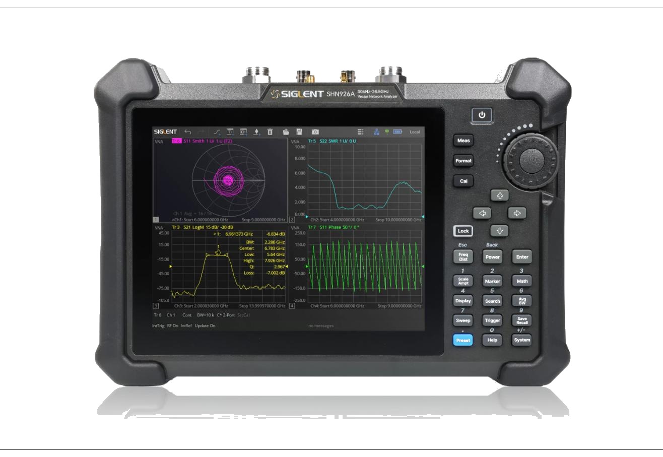
The SHN900A Series is Siglent’s line of handheld, battery-powered vector network analyzers, purpose-built for field testing of cables, antennas, and RF components. Weighing less than 3.2 kg and featuring an 8.4″ multi-touch display, the SHN900A delivers full 2-port S-parameter measurement capability, TDR/TDF fault location, and optional spectrum analysis in a rugged, portable form factor, with up to 4 hours of battery operation for true field use.

Key Features

  • Handheld, battery-operated design weighing less than 3.2 kg
  • 8.4″ multi-touch color display for clear field operation
  • Full 2-port S-parameter measurements with 110 dB typical dynamic range
  • Built-in TDR/TDF analysis for cable and connector fault location
  • SOLT, SOLR, and TRL calibration with impedance conversion and fixture simulation
  • Adjustable differential and single-ended TDR probe support
  • Standard bias-Tee and optional spectrum analysis mode
  • GPS-based time and location tagging for field measurement records
  • Li-ion battery providing up to 4 hours of continuous operation

Product Characteristics

Part NumberPortsFrequency Range
SHN914A230 kHz to 14 GHz
SHN920A230 kHz to 20 GHz
SHN926A230 kHz to 26.5 GHz

All SHN900A Series models share: 110 dB typical dynamic range, 0.003 dB rms / 0.03° rms trace noise, -45 dBm to +10 dBm output power, 10 Hz to 3 MHz IF bandwidth, 1 Hz frequency resolution, 0.01 dB level resolution, 8.4″ multi-touch display, Li-ion battery (up to 4 hours), and dimensions of 310 × 215 × 78.5 mm.


SNA6000A Series Vector Network Analyzer

Product Overview

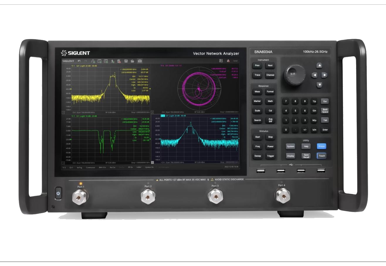
The SIGLENT SNA6000A series is the flagship vector network analyzer platform, covering 100 kHz to 13.5 GHz or 100 kHz to 26.5 GHz across eight 2-port and 4-port models. With 135 dB of dynamic range, standard bias-tee connections, and pulse hardware capability – plus, on the DRA (Direct Receiver Access) variants, a second internal source and direct access to the test-set receivers – the SNA6000A is built for the most demanding R&D, characterization, and high-volume production environments.

Key Features

  • 2-port and 4-port models covering 100 kHz–13.5 GHz and 100 kHz–26.5 GHz
  • 135 dB dynamic range (typ.) with 0.005 dB rms / 0.012° rms trace noise
  • Noise floor down to –135 dBm/Hz (8–20 GHz)
  • DRA (Direct Receiver Access) variants add a second internal source and direct receiver access on 4-port models
  • Standard bias-tee connections and pulse hardware capability
  • 2 to 100,001 measurement points per trace
  • SOLT, SOLR, TRL, Response, and Enhanced Response calibration up to 26.5 GHz
  • LAN, USB Device, USB Host (USB-GPIB); SCPI, LabVIEW, and IVI remote control

Product Characteristics

Part NumberPortsFrequency RangeDirect Receiver Access
SNA6022A2100 kHz – 13.5 GHzNo
SNA6024A4100 kHz – 13.5 GHzNo
SNA6032A2100 kHz – 26.5 GHzNo
SNA6034A4100 kHz – 26.5 GHzNo
SNA6122A2100 kHz – 13.5 GHzYes
SNA6124A4100 kHz – 13.5 GHzYes
SNA6132A2100 kHz – 26.5 GHzYes
SNA6134A4100 kHz – 26.5 GHzYes

All models share 135 dB (typ.) dynamic range, –55 to +10 dBm output level, and 1 Hz–10 MHz IF bandwidth.


SNA5000X-E Series Vector Network Analyzer

Product Overview

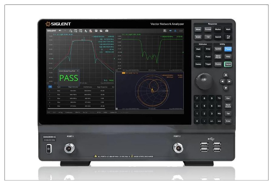
The SIGLENT SNA5000X-E is a compact, cost-effective entry point into the SNA5000 platform, covering 9 kHz to 6.5 GHz across two 2-port models. It retains the SNA5000A family’s core architecture – 125 dB typical dynamic range, a 12.1″ touchscreen, and a standard OCXO timebase – in a lightweight, 5-inch-deep chassis under 12 lbs (5.4 kg), making it a practical choice for R&D, education, and production test where budget and bench space matter.

Key Features

  • Two 2-port models: 9 kHz–3 GHz and 9 kHz–6.5 GHz
  • 125 dB dynamic range (typ.) with 0.006 dB rms / 0.05° rms trace noise
  • Standard OCXO timebase and bias-tee on both ports
  • 12.1″ touchscreen with multi-window display and HDMI output
  • Time-domain analysis, spectrum analysis, and built-in eye-diagram measurement
  • Receiver measurement mode for testing with external RF sources
  • One-click filter characteristic analysis
  • Response, Enhanced Response, Full One-Port, Full Two-Port, and TRL calibration
  • Compact 5-inch-deep chassis, under 12 lbs (5.4 kg)
  • LAN, USB Device, USB Host (USB-GPIB); SCPI, VXI-11, Telnet, WebServer, LabVIEW, and IVI remote control

Product Characteristics

Part NumberPortsFrequency Range
SNA5003X-E29 kHz – 3 GHz
SNA5006X-E29 kHz – 6.5 GHz

Both models share 125 dB (typ.) dynamic range, –40 to +10 dBm output level, 1 Hz–10 MHz IF bandwidth, and 1 Hz frequency resolution.


SDL1000X / SDL1000X-E Series DC Electronic Load

Product Overview

Four models make up the SDL1000X electronic load lineup — SDL1020X, SDL1020X-E, SDL1030X, and SDL1030X-E — each handling up to 150 V and 30 A, with 200 W of headroom on the 1020 models and 300 W on the 1030 models. On top of the usual CC/CV/CR/CP modes, every unit adds battery-discharge testing and a CR-LED mode that mimics an LED’s actual forward voltage/current curve, so driver testing reflects real operating conditions; a 3.5″ TFT-LCD tracks it all with live waveform trending.

Key Features

  • CC/CV/CR/CP static modes plus dynamic (pulsed/toggled) operation
  • Battery discharge testing and CR-LED mode for LED driver evaluation
  • Short-circuit, over-current, over-power, over-voltage, and over-temperature protection
  • 4-wire remote sense compensation
  • Adjustable current slew rate: 0.001–2.5 A/µs
  • Measurement speed up to 500 kHz
  • 3.5″ TFT-LCD display with waveform trending
  • RS232, USB, and LAN standard; USB-GPIB optional

Product Characteristics

SpecSDL1020X-ESDL1020XSDL1030X-ESDL1030X
Voltage / Current150 V / 30 A150 V / 30 A150 V / 30 A150 V / 30 A
Max power200 W200 W300 W300 W
Resolution1 mV / 1 mA0.1 mV / 0.1 mA1 mV / 1 mA0.1 mV / 0.1 mA


SPS5000X Series Wide-Range Programmable Switching DC Power Supply

Product Overview

When a test bench needs both high power and a wide voltage/current window in a compact chassis, the SPS5000X switching supply line covers it across sixteen models, from 50 V to 160 V configurations, each delivering up to 1080 W. Connect units in series for up to 320 V, or in parallel for up to 270 A and a combined 3240 W — a setup built for production test and ATE integration rather than single-bench use.

Key Features

  • 16 models across 40 V, 50 V, 80 V, and 160 V configurations, up to 1080 W each
  • Series operation (2 units, up to 320 V) and parallel operation (3 units, up to 270 A)
  • 2.4″ OLED display with 170° viewing angle
  • USB, LAN, and analog control interfaces standard; optional USB-GPIB
  • Embedded web server for browser-based remote operation
  • Programmable list mode, up to 50 steps
  • Internal discharge circuit for fast voltage ramp-down
  • Remote voltage sensing
  • Overvoltage/overcurrent/low-power/overtemperature protection
  • 1/2, 1/3, and 1/6 rack-mount options
  • 1 mV / 1 mA resolution

Product Characteristics

Part NumberChannelsVoltageCurrent (per channel)Power (per channel)Total power
SPS5041X140 V30 A360 W360 W
SPS5042X140 V60 A720 W720 W
SPS5043X140 V90 A1080 W1080 W
SPS5044X240 V30 A360 W720 W
SPS5045X340 V30 A360 W1080 W
SPS5051X150 V10 A180 W180 W
SPS5081X180 V15 A360 W360 W
SPS5082X180 V30 A720 W720 W
SPS5083X180 V45 A1080 W1080 W
SPS5084X280 V15 A360 W720 W
SPS5085X380 V15 A360 W1080 W
SPS5161X1160 V7.5 A360 W360 W
SPS5162X1160 V15 A720 W720 W
SPS5163X1160 V22.5 A1080 W1080 W
SPS5164X2160 V7.5 A360 W720 W
SPS5165X3160 V7.5 A360 W1080 W

Connect two units in series for up to 320 V, or three units in parallel for up to 270 A and a combined 3240 W.


SPD3303C Programmable DC Power Supply

Product Overview

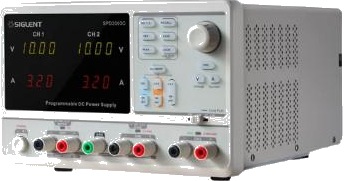
The SPD3303C brings the same 220 W, three-output design as the SPD3303X/X-E — independent, series, and parallel modes included — to classrooms, production lines, and general lab benches at a lower cost. Siglent trades the SPD3303X’s higher-resolution color screen for a simpler LED readout, making this the model to reach for when budget matters more than display precision.

Key Features

  • 3 isolated outputs: 2× 0–32 V/3.2 A + fixed 2.5/3.3/5 V @ 3 A
  • 220 W total output power
  • Independent, series, and parallel output modes
  • LED display: 4-digit voltage, 3-digit current
  • Short-circuit and overload protection
  • USB cable and quick-start guide included
  • In-stock, ships within 1–3 days

Product Characteristics

SpecSPD3303C
Adjustable channels2 × 0–32 V / 0–3.2 A
Fixed channel2.5/3.3/5 V @ 3 A
Total power220 W
DisplayLED, 4-digit V / 3-digit A
Resolution10 mV / 10 mA
Accuracy±(0.5% of reading + 2 digits)


SPD3303X & SPD3303X-E Series Programmable DC Power Supply

Product Overview

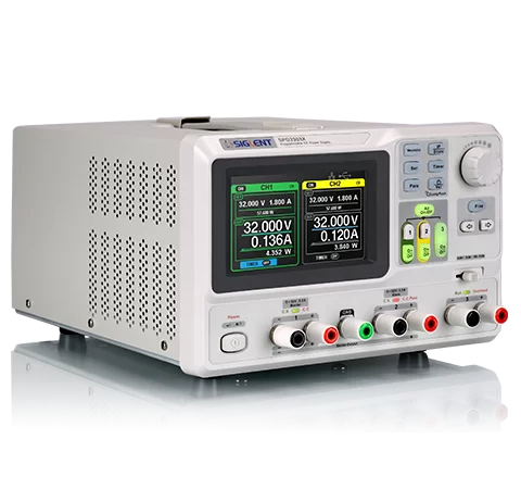
Three isolated, independently controlled outputs live inside one 220 W chassis on the SPD3303X and SPD3303X-E: two adjustable 32 V/3.2 A channels alongside a fixed 2.5 V/3.3 V/5 V rail. The 4.3″ color display plots output waveforms as they happen, and switching between independent, series (to 60 V), and parallel (to 6.4 A) wiring modes lets one supply cover both dual-rail analog circuits and higher-current single-rail loads.

Key Features

  • 3 isolated outputs, 220 W total
  • Independent / series (60 V max) / parallel (6.4 A max) output modes
  • 4.3″ true-color TFT-LCD, 480×272, with real-time waveform display
  • 5 internal memory slots for instrument setups
  • EasyPower PC software and LabVIEW driver included
  • Remote SCPI programming and timing/list functions
  • Universal 100/120/220/230 V AC input, temperature-controlled fan

Product Characteristics

SpecSPD3303XSPD3303X-E
Adjustable channels2 × 0–32 V / 0–3.2 A2 × 0–32 V / 0–3.2 A
Fixed channel2.5/3.3/5 V @ 3.2 A2.5/3.3/5 V @ 3.2 A
Total power220 W220 W
Voltage display5-digit4-digit
Current display4-digit3-digit
Resolution1 mV / 1 mA10 mV / 10 mA
Voltage accuracy±(0.03% + 10 mV)±(0.5% + 2 digits)
Current accuracy±(0.3% + 10 mA)±(0.5% + 2 digits)


SPD1000X Series Programmable DC Power Supply

Product Overview

For a first bench supply, or a compact second unit, the SPD1000X gives students, hobbyists, and engineers accurate, repeatable DC power in a small chassis. Its 2.8″ full-color TFT screen reads voltage to 5 digits and current to 4 digits, resolving down to 1 mV and 1 mA, and each unit comes ready for computer control: EasyPower software, SCPI commands, and a LabVIEW driver are all included for building automated test routines.

Key Features

  • Two models covering 0–16 V/8 A (128 W) and 0–30 V/5 A (150 W)
  • 2.8″ true-color TFT-LCD display, 240×320
  • Voltage accuracy ±(0.03% + 10 mV), current accuracy ±(0.3% + 10 mA)
  • Low ripple & noise: ≤350 µVrms / 3 mVpp, <2 mArms
  • Fast transient response, <50 µs
  • USB remote control with EasyPower PC software, SCPI & LabVIEW drivers
  • 4-wire remote sense compensation (SPD1305X)
  • Save/recall up to 5 instrument setups
  • Universal 100/120/220/230 V AC input, temperature-controlled fan

Product Characteristics

SpecSPD1168XSPD1305X
Voltage/Current0–16 V / 0–8 A0–30 V / 0–5 A
Max power128 W150 W
Display resolution1 mV / 1 mA1 mV / 1 mA
Voltage accuracy±(0.03% + 10 mV)±(0.03% + 10 mV)
Current accuracy±(0.3% + 10 mA)±(0.3% + 10 mA)
InterfaceUSBUSB


Gen 6 High Resolution Tablet Oscilloscope STO Series

High Resolution Automotive Oscilloscope AHO1 Series

High Resolution Automotive Oscilloscope – AHO1 Series

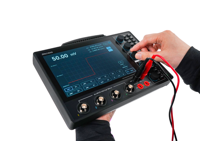
Bandwidth:200MHz

Sampling Rate:1GSa/s

Memory Depth:110Mpts

Analog Channels:4

Display:8 inches, 1280*800

Battery:built-in high-capacity Li-ion battery

OVERVIEW

One tool instead of two.

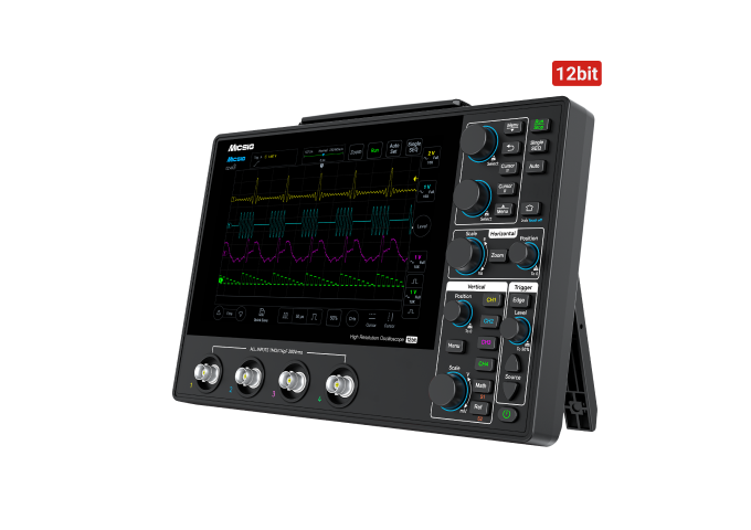
The AHO1 series is Micsig’s high-resolution automotive oscilloscope, built around a 12-bit ADC — 4096 quantization levels, 16 times a standard 8-bit automotive scope — so waveform detail on noisy vehicle signals stays visible instead of buried in quantization noise. A dual general-purpose / automotive software architecture covers dedicated engine, sensor and EV test modes, and a built-in 4⅚-digit multimeter runs alongside the scope with seamless switching, so there’s no second meter to carry. The whole unit is 3.1 cm thick, wrapped in a soft rubber protective casing, and runs on a high-capacity lithium-ion battery rated past 1000 charge cycles with USB-C and power-bank charging.

WHY TECHNICIANS CARRY IT

Eight reasons the AHO1 replaces two tools on the bench.

Each one solves a specific problem with carrying a separate scope and multimeter into mobile or outdoor repair work.

Dual mode

Built for ICE and EV

Automotive and general-purpose oscilloscope software in one unit, with dedicated engine, sensor and EV test modes.

Integrated meter

Skip the second tool

A 4⅚-digit multimeter runs alongside the scope — voltage, current, resistance, continuity, diode and capacitance — with seamless switching.

Resolution

See what 8-bit scopes miss

12-bit ADC, 4096 quantization levels — 16x a standard 8-bit automotive scope — for cleaner detail on noisy vehicle signals.

Portability

3.1 cm, full stop

An ultra-thin body in a soft rubber protective casing, built to go in a service bag, not stay on a bench.

Battery

A shift, not a session

High-capacity Li-ion battery rated past 1000 charge cycles, with USB-C and power-bank charging for a full day in the bay.

Storage

Multiple triggers, one capture

Standard segmented storage splits memory into segments so several trigger events land in one recording, reviewable individually or together.

Control

However you want to run it

Full touchscreen, physical buttons and knobs, or a hybrid of both, on the SigTest UI.

Connectivity

Remote-ready

SCPI programmability, mobile app and PC control, plus direct HDMI output with no drivers to install.

WHERE IT’S USED

Built for the vehicle systems that punish ordinary scopes.

From routine charging-circuit checks to CAN/LIN network debugging on both combustion and electric platforms, the AHO1 is sized and powered for mobile and outdoor diagnostic work.

  • Charging & starting circuits
  • Sensors and actuators
  • Ignition systems
  • CAN L/H, CAN FD and LIN networks
  • FlexRay and K-line networks
  • Combination / multi-bus tests
  • ICE and EV / hybrid diagnostics
  • Mobile and outdoor repair work

KEY SPECIFICATIONS

AHO14-200, in full.

The current AHO1 series configuration — full attenuator and accessory options available on request.

ModelAHO14-200
Bandwidth200 MHz
Analog Channels4
Real-time Sampling Rate1 GSa/s
Rise Time≤ 1.75 ns
Memory Depth110 Mpts
Vertical Resolution12-bit
Max. Waveform Capture Rate50,000 wfms/s
InterfacesUSB 3.0 Host, USB Type-C, LAN, HDMI
Support TestCharging/Start Circuits, Sensors, Actuators, Ignition, Networks (CAN L/H, CAN FD, LIN, Flexray, K-line), Combination Tests
Display8″ TFT LCD capacitive touchscreen, 1280×800 pixels
Battery3.7 V, 16,000 mAh lithium-ion battery
ChargingStandard DC 12V adapter; supports Type-C 5V charging
Multifunction Meter Accuracy4⅚ Digits
Dimension265 × 174 × 31 mm (W×H×Thickness)

DOCUMENTATION

Documentation

SCPI Programming Guide — Micsig Oscilloscope
PDF · 584 KB

Download →

User Manual — AHO1 Series
PDF · 27.2 MB

Download →

Need to spec an automotive scope for your shop?

Pertech is Micsig’s authorized reseller in Israel. Tell us how many channels and which vehicle systems you’re testing, and we’ll confirm the right AHO1 configuration and accessory kit.

Pertech Embedded Solutions · Ra’anana, Israel · pertech.co.il

I3C Electrical Validation Software

PGY-I3C Electrical Validation Software

The PGY-I3C Electrical Validation Software from Prodigy Technovations is a comprehensive compliance and debug solution designed for engineers developing and validating I3C interfaces. Running directly on supported Tektronix oscilloscopes, the software automates electrical measurements, protocol correlation, and waveform analysis to significantly reduce debug time and accelerate product development.

Automated I3C Electrical Compliance Testing

The software performs automated electrical measurements according to the I3C specification, including support for:

* Fast Mode
* Fast Mode Plus
* Open Drain mode
* Push-Pull mode
* SDR and HDR-DDR timing analysis
* I2C legacy device communication validation

Engineers can automatically verify critical timing and electrical parameters such as clock frequency, rise/fall times, setup and hold timing, bus free conditions, and spike suppression requirements.

Deep Correlation Between Protocol and Physical Layer

One of the key strengths of the PGY-I3C platform is its ability to directly correlate decoded protocol packets with analog waveforms on the oscilloscope. Engineers can instantly jump from a protocol event in the decode table to the corresponding electrical waveform for rapid root-cause analysis.

The software provides:

* Linked protocol decode and waveform visualization
* Detailed packet-level electrical analysis
* Zoom-to-event capability
* Worst-case measurement identification
* Multi-acquisition debug correlation

This dramatically simplifies debugging of intermittent or marginal I3C timing issues.

Flexible Characterization Beyond Compliance

Unlike basic compliance tools, PGY-I3C allows engineers to customize reference levels and measurement limits for advanced characterization and margin testing. This enables validation teams to evaluate device performance beyond specification limits and better understand system robustness under varying conditions.

Powerful Debug Environment

The integrated debug environment helps engineers quickly isolate failures and investigate waveform behavior with:

* Detailed analog waveform inspection
* Cursor and marker utilities
* Interactive zoom controls
* Worst-case acquisition tracking
* Measurement correlation across multiple captures

The Detail View combines protocol decode, waveform display, and electrical measurements in a single screen for highly efficient analysis.

Offline Analysis and Reporting

PGY-I3C supports:

* WFM file import for offline analysis
* CSV and TXT export of measurement data
* Automated report generation

This makes it easy to document compliance results, share findings across engineering teams, and maintain validation records.

Supported Oscilloscopes

The software is designed for Tektronix oscilloscope platforms including:

* DPO/MSO5000 series
* DPO7000 series
* DPO/MSO/DSA70000 series
* MSO5 series
* MSO6 series

The license is locked to the oscilloscope platform for seamless deployment in validation laboratories.

Ideal Applications

PGY-I3C Electrical Validation Software is ideal for:

* Semiconductor validation labs
* Embedded systems development
* Sensor and mobile platform validation
* Automotive electronics development
* High-speed serial interface characterization
* Compliance and interoperability testing

The solution helps design and validation teams improve measurement accuracy, reduce manual analysis effort, and shorten development cycles for modern I3C-based systems.

esReverse – Reverse Engineering Without Limits

Dediprog -SF600plus – spi nor flash development kit

Special price

Limited stock at a special price. SFDK03-G2 kits are in stock at Pertech. For the newer model, see the SF600Plus-G2.

Ask for the price

Dediprog -SF600plus – spi nor flash development kit – SFDK03-G2

description

SPI Flash Development kit gives engineers the total solution while working on firmware development based on the SPI flash memories.

This kit combines all the accessories of EM100Pro-G2 and SF600Plus and gives the users greater price advantages than purchasing separately.

For more information, please visit SF600Plus and EM100Pro-G2 product page.

SFDK03-G2 Highlights

  • SF600Plus and its accessories x 1
  • EM100Pro-G2 and its accessories x 1

Key Specifications

SpecValue
StatusLegacy kit — replaced by SF600Plus-G2
Kit ContentsSF600 Plus + accessories x1, EM100Pro-G2 + accessories x1
Use CaseCombined ISP programming + SPI flash emulation development kit
Base ProductsSF600 Plus, EM100Pro-G2

Dediprog – SF700 SPI Flash Programmer

SF700 SPI Flash Programmer

This product was replaced by SF600Plus-G2

description

SF700 is a all-new designed SPI Flash engineering programmer, which supports all SPI NOR Flash and SPI NAND Flash in the market.
SF700 continues to provide strong engineering mode and command line as SF600, DediProg’s another programmer, to satisfy the
demand for R&D.


Apart from the engineering application, SF700 also supports projectfile for small volume production demand. SF700 can do programming in parallel with multiple programmers or
Standalone mode.

SF700 Highlights

  • USB High speed and high SPI performance, support up to 2Gb SPI Flash
  • In-Circuit Programming: Program on board SPI Flash
  • Off-line Programming: Program SPI Flash in the socket
  • Start button feature: Able to Batch in the USB mode
  • Standalone mode: Support Start button programming and IO Port programming.
  • ISP Port supports 2 CS pins to program two Serial Flash memories
  • Signal conflict protections
  • Multi-Programmers Capability through USB
  • Support 1.8V low voltage IC
  • Support Windows 2003 and above
  • Support both 32 and 64 bit OS

Files and media

Dediprog – SF100 ISP Evaluation Kit

SF100 ISP Evaluation Kit

description

In System Programming (ISP) method Description:
Update your SPI Flash soldered on your application board by using our dedicated programmers: SF100. When connected to the application board, the SF100 programmer can control the SPI bus to read or update the Serial Flash content in a very short time.

ISP-Eval-01 Highlights

  • SF100 programmer to update the serial Flash on board x 1
  • ISP Evaluation board: To test and validate the ISP method x 1
  • 1.27mm 2*4 cable: to connect the ISP evaluation board to the application x 1
  • SMT 1.27mm connectors: to solder in place of your application serial Flash x 2
  • Resistors: 100 Ohm for safe SPI isolation trials x 10
  • Resistors: 47 Ohm for tuned SPI isolation trials x 10
  • N MOSFET for SPI and Vcc isolation trials x 10
  • Resistors: 0 Ohm for Vcc short cut x 2
  • Diodes: for Vcc isolation trials x 2
  • Cables with a test clip: to connect the application powers and reset to the ISP evaluation board x 3

Key Specifications

SpecValue
Kit ContentsSF100 programmer x1, ISP Evaluation board x1
Cable1.27mm 2×4 ISP cable
Included ComponentsSMT 1.27mm connectors x2, isolation resistors/MOSFETs/diodes for SPI & Vcc isolation trials
Use CaseTest and validate the ISP method before board design

Dediprog – SF100 SPI NOR Flash Programmer

SF100 SPI NOR Flash Programmer

Key Specifications

SpecValue
InterfaceUSB, 2×7 ISP header, 1 CS pin
Supported FlashSPI NOR Flash (W25X80, W25Q series, S25FL512, etc.)
MCU SupportFreescale MCU internal Flash via Ezport / external via SBF
Dual FlashCapable of handling two serial flash memories simultaneously
Programming Speed11s (8Mb) – 297s (512Mb)
ModesISP, Engineering Mode, Production Mode, CLI
OS SupportWindows 2003+ (32/64-bit), Linux (GitHub)

SF600Plus-G2 SPI NOR Flash Programmer

SF600Plus-G2 SPI NOR Flash Programmer

SF600Plus-G2 is a high-speed Serial NOR/NAND Flash programmer with In-Circuit Programming (update the SPI Flash soldered on board) and Standalone programming (update the SPI Flash in the socket adaptor) Mode.


With DediProg SF software and the USB, it offers friendly user interfaces and powerful features.

The newly designed SF600Plus-G2 is the upgraded version of SF600 and SF600Plus, which greatly increases the programming efficiency with the SOC architecture of FPGA.


Other than the original functions of the SF600/S600Plus, it can also support SPI NAND, which will be convenient for the developer when programming.

SF600Plus-G2 Highlights

  • High-speed USB and high SPI performance; the USB and Standalone mode support any volume of the SPI Flash on the market.
  • Support 1.2V low voltage IC.
  • Start button feature: Able to Batch when connecting to the software.
  • Signal conflict protections.
  • Multi-Programmers Capability through USB.
  • Programmer Index displays on the programmer.
  • Support 2 CS pins.
  • Stand-Alone Mode: Support Start button programming and Control Port for removing control programming.
  • Support WIN8 and above.
  • Support both 32 and 64bit OS.
  • Support Single/Dual Multiple Dies.
  • Support Single/Dual/Quad/Octal. IO.
  • Able to upgrade to SF600Plus-G2U.

Files and media

Key Specifications

SpecValue
Supported FlashSPI NOR / SPI NAND, Single/Dual/Quad/Octal IO
InterfaceUSB 2.0, 2 CS pins
VoltageDown to 1.2V low-voltage ICs
ModesIn-Circuit Programming (ICP) & Stand-Alone (socket adaptor)
Programming Speed8Mb flash ≈ 6.3s via USB @25MHz Quad I/O
OS SupportWindows 32-bit / 64-bit

Dediprog – SF600 SPI NOR Flash Programmer

SF600 SPI NOR Flash Programmer

This product was replaced by SF600Plus-G2​

The SF600 is a high-speed “in System Programming” programmer to update the SPI Flash soldered on board (In-Circuit Programming) or in the socket adaptor (Offline programming). The programmer is easily controlled by the computer DediProg Software through the USB bus offering a friendly interface and powerful features to users.

SF600 combines the advantages of SF100 with additional improvements: High-speed USB and higher SPI performances.


SF600Plus Highlights

  • USB High speed and high SPI performance, support up to 2Gb SPI Flash
  • In circuit Programming: Program on-board SPI Flash
  • Offline Programming: Program SPI Flash in the socket
  • ISP Port supports 2 CS pins to program two Serial Flash memories
  • Start button feature: Able to Batch in the USB mode
  • Signal conflict protections
  • Multi-Programmers Capability through USB
  • Support 1.8V low voltage IC
  • Support Windows 2003 and above
  • Support both 32 and 64-bit OS


Files and media

https://pertech.co.il/wp-content/uploads/2020/10/SF600_SF600Plus-Flyer_EN.pdf

Binho – I3C Basic Protocol Analyzer

I3C Basic℠ Protocol Analyzer Plugin for Saleae Logic

Binho is proud to introduce the first I3C BasicSM Protocol Analyzer for firmware development and embedded systems testing. Leave that stack of silicon-validation equipment in the lab, speed up development, and save a pile of money all at the same time.

Binho - I3C Basic Protocol Analyzer – I3C Basic℠ Protocol Analyzer Plugin for Saleae Logic

Binho Pulsar

Binho Pulsar

The Binho Pulsar USB Host Adapter allows one to interface a PC directly to hardware circuits. Featuring a USB 2.0 High Speed 480 Mbps link to the host, the Pulsar offers an unmatched value proposition in the test tool market. The Pulsar features a modern USB Type-C port, 5 x RGB LEDs for visual status indication, and a variety of DUT-facing connections all in a compact, robust machined-aluminum enclosure including integrated mounting holes.

The host adapter is able to communicate on many digital buses: I2C, SPI, UART, RS-485, 1-Wire, and CAN-FD. All of these protocols are implemented on their own dedicated pins and can be operated simultaneously. A bank of 6 x dedicated digital GPIO pins can be assigned to other related or unrelated purposes such as GPIO, interrupts, resets, chip selects, etc, as well as operating as digital PWM outputs.

Key Features

  • USB High Speed 480Mbps Connection to Host PC
  • Support for SPI protocol
    • SPI Controller
    • All 4 SPI Modes Supported
    • Up to 50 MHz max clock speed
    • Up to 4 x CS signals
    • Configurable MSB/LSB
    • SPI Peripheral (coming soon)
    • Voltage range from 1.2V to 3.3V
  • Support for I2C protocol
    • I2C Controller
    • 1 MHz max clock speed
    • 7-bit Addressing, Clock Stretching
    • Configurable Pull-up Resistors
    • 10-bit Addressing (coming soon)
    • I2C Peripheral (coming soon)
    • Voltage range from 1.2V to 3.3V
  • Support for UART protocol
    • 115200 max baud
    • Support for Hardware Flow Control
    • Voltage range from 1.2V to 3.3V
  • Support for RS-485
    • -7V to +12V Common-Mode Input
    • Half-Duplex
  • Support for CAN-FD Protocol (coming soon)
    • Optimized for use in 12V systems
    • Up to 5 Mbps data rate
  • Support for 1-Wire Protocol (coming soon)
    • Standard and Overdrive speeds
    • 3.3V and 5V operation
  • GPIO pins
    • 6 x Digital IO pins
    • Voltage range from 1.2V to 3.3V
    • Configurable as Interrupts
    • PWM Support (coming soon)
  • Provides downstream power to DUT
    • Programmable from 1.2V to 3.3V
  • Robust Machined Aluminum Enclosure
    • 5 x RGB Status LEDS
    • Integrated mounting holes
    • Silent, Fanless design
  • All cables and accessories included
    • Stored in custom zippered case
  • Full-featured Software Support
    • Point-and-Click GUI
    • Cross-Platform:  Windows, Mac, Linux
    • Python, C/C#/C++ SDKs
    • Field-Upgradeable Device Firmware

Target Applications

  • Device Driver Development
  • Firmware Development & Verification
  • Proof of Concept Development
  • Automated HW/FW Testing
  • FLASH & EEPROM Programming

The full product datasheet is available at the link below:
Binho Pulsar Product Datasheet

PEEDI – JTAG/SWD/BDM Flash Programmer

Ronetix PEEDI Flash Programmer is a JTAG, SWD and BDM flash programmer for development and production. It programs NOR, NAND, SPI flash, eMMC, EEPROM and MCU on-chip flash, from a telnet or serial console at your desk, or standalone on a production line with up to 15 images on an SD card and two front-panel buttons. It is the PEEDI emulator without the debugger, and it can be upgraded to the full emulator at any time. Pertech is a Ronetix distributor.

PEEDI Flash Programmer highlights

  • Programs through JTAG, SWD or BDM
  • NOR, SPI NOR, DataFlash, NAND, OneNAND, eMMC, MMC/SD, I2C EEPROM, FPGA/CPLD and MCU flash
  • Standalone: up to 15 images on SD card, chosen on the front panel, no PC needed
  • Auto-program when target power is detected
  • Images from TFTP, FTP, HTTP or SD card; telnet, serial and TCL scripting
  • Up to 4 targets at once with a multi-programming license
  • Upgradeable to the PEEDI Emulator and Flash Programmer

Where the PEEDI Flash Programmer fits

  • Production lines that program flash or eMMC on assembled boards
  • Programming boot loaders such as U-Boot into a new board
  • Field service and rework stations
  • Teams that need programming now and may need debugging later

Key Specifications

SpecValue
ModelPEEDI JTAG/SWD/BDM Flash Programmer
InterfacesJTAG, SWD, BDM
DebuggerNone (upgradeable to the Emulator version)
JTAG/BDM clockUp to 33 MHz JTAG (22 MHz BDM), adaptive clocking
Target voltageAutosense, 1.2 V to 5 V
Host connectionEthernet 10/100BASE-T; RS232 for setup
Flash devicesNOR (with and without CFI), SPI NOR and SPI DataFlash, NAND with various ECC methods, OneNAND, MMC/SD and eMMC, I2C EEPROM, FPGA/CPLD (JBC player), on-chip flash of many MCUs
Image sourcesTFTP, FTP or HTTP server, or the MMC/SD card
ControlTelnet or serial command line, TCL scripts, front panel
Multi-targetUp to 4 target boards per adapter with a multi-programming license
Front panel2 buttons and a 7-segment LED; status LEDs for power, target power, Ethernet and JTAG/BDM
Image storageMMC/SD card, up to 15 images selectable on the front panel
Power5 V / 1 A; 6.9 V overvoltage shutdown
CaseAluminium, 115 x 105 x 34 mm, 270 g
WarrantyHardware 3 years, software 1 year

Frequently asked questions

What is the PEEDI Flash Programmer?

It is the Ronetix PEEDI hardware with the flash-programming functions only. It programs flash through JTAG, SWD or BDM, from a console during development or standalone on a production line.

How does it differ from the PEEDI Emulator?

It has no source-level debugger support, so it cannot be used with GDB. Everything else, including standalone programming and the supported flash devices, is the same. See the PEEDI JTAG/SWD/BDM Emulator and Flash Programmer.

Can I upgrade it to the Emulator later?

Yes. Ronetix states that a PEEDI Flash Programmer can be upgraded to the Emulator and Flash Programmer at any time.

How does standalone production programming work?

Copy up to 15 images to the MMC/SD card. The operator picks an image with the front-panel buttons and PEEDI programs the board without a PC. It can start automatically when it detects target power.

Can it program several boards at once?

Yes, up to four targets, with a multi-programming license and a multicore adapter.

Which flash devices can it program?

NOR flash with or without CFI, SPI NOR and DataFlash, NAND with various ECC methods, OneNAND, MMC/SD and eMMC, I2C EEPROM, FPGA/CPLD through a JBC player, and the on-chip flash of many MCUs from NXP, ST, Microchip, Renesas, Nordic, TI and others.

Where can I buy it in Israel?

Pertech is a Ronetix distributor in Israel. Contact Pertech for a quote, the right adapter and a production setup that fits your line.

Related Ronetix products at Pertech

Setting up production programming? Contact Pertech for a quote or help planning the setup.


PEEDI – JTAG/SWD/BDM Emulator and Flash Programmer

Ronetix PEEDI is a JTAG, SWD and BDM emulator and flash programmer that sits on your Ethernet network and talks GDB. Its standout capability is Linux kernel and driver debugging: with the MMU enabled, you can stop the kernel, set breakpoints in a driver and see every thread, from Eclipse or any GDB front end. The same box programs NOR, NAND, SPI flash and eMMC, at a desk or standalone on a production line. Pertech is a Ronetix distributor.

PEEDI highlights

  • Linux kernel, driver and application debugging over GDB, also with the MMU enabled
  • OS awareness (“info threads”) for Linux, uClinux and eCos
  • Hardware and software breakpoints; target reset control and remote reset detection
  • Works with Eclipse, Insight, ddd and any GDB remote-protocol debugger
  • Arm (Cortex-A, Cortex-R, Cortex-M, ARM7/9/11, XScale), Power Architecture, ColdFire, Blackfin, MIPS and AVR32
  • Built-in flash programmer for NOR, NAND, OneNAND, SPI flash, eMMC, EEPROM and FPGA/CPLD
  • Standalone mode: up to 15 images on an SD card, selected on the front panel
  • Ethernet connection, so a target in the lab can be debugged from anywhere on the network

How Linux kernel debugging with PEEDI works

Connect PEEDI to the target’s JTAG or SWD header and to your network. PEEDI initializes the processor on power-up or reset and acts as a GDB server over Ethernet. Point GDB or Eclipse at PEEDI with your kernel’s vmlinux symbols, and you can halt the kernel, step through driver code, inspect memory and list threads. Because PEEDI handles debugging with the MMU enabled, you can follow code after the kernel turns on virtual memory, which is where many board bring-up problems hide.

Where PEEDI fits

  • Board bring-up: U-Boot, device tree and early kernel boot
  • Linux driver development and kernel crash analysis
  • RTOS and bare-metal debugging on Cortex-M and Cortex-R MCUs
  • Production programming of flash and eMMC without a PC
  • Remote labs, where targets sit in another room or site

Key Specifications

SpecValue
ModelPEEDI JTAG/SWD/BDM Emulator and Flash Programmer
InterfacesJTAG, SWD, BDM
DebuggerGNU GDB remote protocol: Eclipse, Insight, ddd; OS awareness for Linux, uClinux, eCos
JTAG/BDM clockUp to 33 MHz JTAG (22 MHz BDM), adaptive clocking
Target voltageAutosense, 1.2 V to 5 V
Host connectionEthernet 10/100BASE-T; RS232 for setup
Flash devicesNOR (with and without CFI), SPI NOR and SPI DataFlash, NAND with various ECC methods, OneNAND, MMC/SD and eMMC, I2C EEPROM, FPGA/CPLD (JBC player), on-chip flash of many MCUs
Image sourcesTFTP, FTP or HTTP server, or the MMC/SD card
ControlTelnet or serial command line, TCL scripts, front panel
Multi-targetUp to 4 target boards per adapter with a multi-programming license
Front panel2 buttons and a 7-segment LED; status LEDs for power, target power, Ethernet and JTAG/BDM
Image storageMMC/SD card, up to 15 images selectable on the front panel
Power5 V / 1 A; 6.9 V overvoltage shutdown
CaseAluminium, 115 x 105 x 34 mm, 270 g
WarrantyHardware 3 years, software 1 year

Frequently asked questions

What is PEEDI?

PEEDI (Powerful Embedded Ethernet Debug Interface) is a Ronetix JTAG, SWD and BDM emulator and flash programmer. It connects to your network over Ethernet and serves GDB, so you can debug and program embedded targets from any PC on the network.

Can PEEDI debug the Linux kernel and drivers?

Yes. PEEDI supports Linux kernel and application debugging through GDB, also when the MMU is enabled, with OS awareness (“info threads”) for Linux, uClinux and eCos. You can set hardware and software breakpoints in kernel code and drivers.

Which debuggers work with PEEDI?

Any GNU GDB based debugger using the GDB remote protocol, including Eclipse, Insight and ddd. Ronetix also provides pre-built GNU cross toolchains.

Which processor families are supported?

Arm (ARM7, ARM9, ARM11, XScale, Cortex-M0 to M33, Cortex-R4F, Cortex-A5 to A72 including 64-bit Armv8), Power Architecture (MPC5xxx, QorIQ, including 64-bit e5500 and e6500), ColdFire, Analog Devices Blackfin, MIPS32, MIPS64 and AVR32.

Can it program flash without a PC?

Yes. Store up to 15 images on the MMC/SD card, pick one on the front panel and PEEDI programs the target on its own, optionally as soon as it detects target power. This makes it a production-line programmer as well as a debugger.

Can I debug or program several boards at once?

Multicore CPUs are supported without an extra license. Working on multiple boards at once needs an extra license and a multicore adapter, which controls up to 4 target boards.

Which JTAG adapter do I need?

It depends on your target connector. Ronetix makes adapters for ARM-20, ARM-14, Cortex-20, Cortex-10, TI-14, COP-16, Nexus-14, BDM-26, Blackfin-14, MIPS-14 and AVR32, plus 4-target multicore adapters. Pertech will help you choose.

What is the difference between the Emulator and the Flash Programmer?

The Flash Programmer has the same hardware and flash features but no source-level debugger support. It can be upgraded to the Emulator and Flash Programmer at any time. See the PEEDI JTAG/SWD/BDM Flash Programmer.

Where can I buy PEEDI in Israel?

Pertech is a Ronetix distributor in Israel. Contact Pertech for a quote, the right adapter for your target and technical support. PEEDI carries a three-year hardware warranty and a one-year software warranty.

Related Ronetix products at Pertech

Bringing up a Linux board? Contact Pertech for a quote, the right JTAG adapter or a demo.


Algocraft WriteNow! 8 WN-PRG08A – 8-Site In-System Programmer

Algocraft WriteNow! 8 (WN-PRG08A) is a 8-site in-system programmer that programs 8 devices in true parallel on the assembled board. Each site can run its own image, and variable data such as serial numbers and MAC addresses can be different on every site in every cycle. It fits inside a test fixture, is controlled by an ATE or a PC, or runs standalone from projects on its memory card. Pertech is an Algocraft distributor.

WriteNow! 8 highlights

  • 8 programming sites, true parallel programming
  • Each site can run its own image; per-site serial numbers, MAC addresses and production codes
  • Microcontrollers, serial and parallel memories, CPLDs and other programmable devices
  • JTAG, SWD, SPI/QSPI, I2C, UART, BDM, SWIM, ICSP, UPDI, SBW and many more protocols
  • Programmable I/O voltage 1.6 to 5.5 V, high-speed I/O, EOS/ESD protection
  • Isolated LAN, isolated RS-232, USB and an isolated low-level interface for ATE control
  • Standalone operation from projects on the built-in memory card
  • SDK/API for Visual C, Visual Basic, C# and LabVIEW, plus an ASCII command protocol
  • Expands to more ISP channels with a demultiplexer module (up to 32)

Where the WriteNow! 8 fits

  • In-circuit and functional test stations (Keysight, Teradyne, TRI, SPEA, SEICA)
  • Panels of boards programmed in one cycle
  • Automotive production with PSI5 and differential-bus adapters
  • Lines that need serial numbers, MAC addresses or calibration data per board

Key Specifications

SpecValue
ModelWN-PRG08A
Programming sites8
Device typesMicrocontrollers, CPLDs, serial memories, programmable ICs
Programming protocolsJTAG, SWD, UART, SPI/QSPI, BDM, SWIM, I2C, DAP, cJTAG, C2, ICSP, PDI, UPDI, FINE, MUST/MICE, MON08, ISSP, ICC, MDI, OUT, PSI5, SBW and custom
ISP linesAdjustable voltage 1.6 to 5.5 V (100 mV steps); 48 bidirectional lines, 8 output lines
Programmable power supply8 channels
Host interfacesRS-232 (isolated), LAN 100 Mbit/s (isolated), USB full speed
Low-level interface (isolated)START, START_ENA[1..8], OK/ERR[1..8], BUSY, PRJ_SEL[0..5]
Relay barrierOptional module WN-REB08A
Demultiplexer moduleWN-DM8X2A (16 channels), WN-DM8X3A (24), WN-DM8X4A (32)
Power supply15 to 24 V
Dimensions153 x 110 x 29 mm with enclosure
Package contentsWriteNow! unit, 15 V power supply, RS-232/USB/LAN cables, test board, 48-way female wire-wrap connector

Frequently asked questions

What is the WriteNow! 8 WN-PRG08A?

It is an Algocraft in-system programmer with 8 programming sites that work in true parallel, for programming devices on the assembled board in production.

Can each site program a different image?

Yes. A programming command runs a project on the sites you select, so different sites can run different projects, and variable data such as serial numbers can be different for each site. Over the low-level interface, PRJ_SEL lines select the project and START_ENA lines enable each site.

Can I add more channels?

Yes. Algocraft demultiplexer modules multiply the ISP lines: WN-DM8X2A (16 channels), WN-DM8X3A (24), WN-DM8X4A (32).

How is it controlled on the production line?

Standalone with the START line, from a PC with the Algocraft software, or from an ATE through isolated LAN, RS-232 or the low-level interface, using the ASCII command protocol or the SDK for Visual C, Visual Basic, C# and LabVIEW.

Which WriteNow! model do I need?

Pick the number of sites to match the boards you program per cycle: WriteNow! (1 site, relay barrier built in), WriteNow! 2, 4 or 8. All models share the same software and projects, and the single-site µISP is compatible with them for lab work.

Where can I buy the WriteNow! 8 WN-PRG08A in Israel?

Pertech is an Algocraft distributor in Israel. Contact Pertech for a quote, a check that your devices are supported, or help planning the programming station.

Related Algocraft products at Pertech

Planning a programming station? Contact Pertech for a quote, a demo or a device support check.


Algocraft WriteNow! 4 WN-PRG04A – 4-Site In-System Programmer

Algocraft WriteNow! 4 (WN-PRG04A) is a 4-site in-system programmer that programs 4 devices in true parallel on the assembled board. Each site can run its own image, and variable data such as serial numbers and MAC addresses can be different on every site in every cycle. It fits inside a test fixture, is controlled by an ATE or a PC, or runs standalone from projects on its memory card. Pertech is an Algocraft distributor.

WriteNow! 4 highlights

  • 4 programming sites, true parallel programming
  • Each site can run its own image; per-site serial numbers, MAC addresses and production codes
  • Microcontrollers, serial and parallel memories, CPLDs and other programmable devices
  • JTAG, SWD, SPI/QSPI, I2C, UART, BDM, SWIM, ICSP, UPDI, SBW and many more protocols
  • Programmable I/O voltage 1.6 to 5.5 V, high-speed I/O, EOS/ESD protection
  • Isolated LAN, isolated RS-232, USB and an isolated low-level interface for ATE control
  • Standalone operation from projects on the built-in memory card
  • SDK/API for Visual C, Visual Basic, C# and LabVIEW, plus an ASCII command protocol
  • Expands to more ISP channels with a demultiplexer module (up to 16)

Where the WriteNow! 4 fits

  • In-circuit and functional test stations (Keysight, Teradyne, TRI, SPEA, SEICA)
  • Panels of boards programmed in one cycle
  • Automotive production with PSI5 and differential-bus adapters
  • Lines that need serial numbers, MAC addresses or calibration data per board

Key Specifications

SpecValue
ModelWN-PRG04A
Programming sites4
Device typesMicrocontrollers, CPLDs, serial memories, programmable ICs
Programming protocolsJTAG, SWD, UART, SPI/QSPI, BDM, SWIM, I2C, DAP, cJTAG, C2, ICSP, PDI, UPDI, FINE, MUST/MICE, MON08, ISSP, ICC, MDI, OUT, PSI5, SBW and custom
ISP linesAdjustable voltage 1.6 to 5.5 V (100 mV steps); 24 bidirectional lines, 4 output lines
Programmable power supply4 channels
Host interfacesRS-232 (isolated), LAN 100 Mbit/s (isolated), USB full speed
Low-level interface (isolated)START, START_ENA[1..4], OK/ERR[1..4], BUSY, PRJ_SEL[0..5]
Relay barrierOptional module WN-REB04A
Demultiplexer moduleWN-DM4X2A (8 channels), WN-DM4X3A (12), WN-DM4X4A (16)
Power supply15 to 24 V
Dimensions153 x 110 x 29 mm with enclosure
Package contentsWriteNow! unit, 15 V power supply, RS-232/USB/LAN cables, test board, 48-way female wire-wrap connector

Frequently asked questions

What is the WriteNow! 4 WN-PRG04A?

It is an Algocraft in-system programmer with 4 programming sites that work in true parallel, for programming devices on the assembled board in production.

Can each site program a different image?

Yes. A programming command runs a project on the sites you select, so different sites can run different projects, and variable data such as serial numbers can be different for each site. Over the low-level interface, PRJ_SEL lines select the project and START_ENA lines enable each site.

Can I add more channels?

Yes. Algocraft demultiplexer modules multiply the ISP lines: WN-DM4X2A (8 channels), WN-DM4X3A (12), WN-DM4X4A (16).

How is it controlled on the production line?

Standalone with the START line, from a PC with the Algocraft software, or from an ATE through isolated LAN, RS-232 or the low-level interface, using the ASCII command protocol or the SDK for Visual C, Visual Basic, C# and LabVIEW.

Which WriteNow! model do I need?

Pick the number of sites to match the boards you program per cycle: WriteNow! (1 site, relay barrier built in), WriteNow! 2, 4 or 8. All models share the same software and projects, and the single-site µISP is compatible with them for lab work.

Where can I buy the WriteNow! 4 WN-PRG04A in Israel?

Pertech is an Algocraft distributor in Israel. Contact Pertech for a quote, a check that your devices are supported, or help planning the programming station.

Related Algocraft products at Pertech

Planning a programming station? Contact Pertech for a quote, a demo or a device support check.


Algocraft WriteNow! 2 WN-PRG02A – 2-Site In-System Programmer

Algocraft WriteNow! 2 (WN-PRG02A) is a 2-site in-system programmer that programs 2 devices in true parallel on the assembled board. Each site can run its own image, and variable data such as serial numbers and MAC addresses can be different on every site in every cycle. It fits inside a test fixture, is controlled by an ATE or a PC, or runs standalone from projects on its memory card. Pertech is an Algocraft distributor.

WriteNow! 2 highlights

  • 2 programming sites, true parallel programming
  • Each site can run its own image; per-site serial numbers, MAC addresses and production codes
  • Microcontrollers, serial and parallel memories, CPLDs and other programmable devices
  • JTAG, SWD, SPI/QSPI, I2C, UART, BDM, SWIM, ICSP, UPDI, SBW and many more protocols
  • Programmable I/O voltage 1.6 to 5.5 V, high-speed I/O, EOS/ESD protection
  • Isolated LAN, isolated RS-232, USB and an isolated low-level interface for ATE control
  • Standalone operation from projects on the built-in memory card
  • SDK/API for Visual C, Visual Basic, C# and LabVIEW, plus an ASCII command protocol
  • Expands to more ISP channels with a demultiplexer module (up to 8)

Where the WriteNow! 2 fits

  • In-circuit and functional test stations (Keysight, Teradyne, TRI, SPEA, SEICA)
  • Panels of boards programmed in one cycle
  • Automotive production with PSI5 and differential-bus adapters
  • Lines that need serial numbers, MAC addresses or calibration data per board

Key Specifications

SpecValue
ModelWN-PRG02A
Programming sites2
Device typesMicrocontrollers, CPLDs, serial memories, programmable ICs
Programming protocolsJTAG, SWD, UART, SPI/QSPI, BDM, SWIM, I2C, DAP, cJTAG, C2, ICSP, PDI, UPDI, FINE, MUST/MICE, MON08, ISSP, ICC, MDI, OUT, PSI5, SBW and custom
ISP linesAdjustable voltage 1.6 to 5.5 V (100 mV steps); 12 bidirectional lines, 2 output lines
Programmable power supply2 channels
Host interfacesRS-232 (isolated), LAN 100 Mbit/s (isolated), USB full speed
Low-level interface (isolated)START, START_ENA[1..2], OK/ERR[1..2], BUSY, PRJ_SEL[0..5]
Relay barrierOptional module WN-REB02A
Demultiplexer moduleWN-DM2X2A (4 channels), WN-DM2X3A (6), WN-DM2X4A (8)
Power supply15 to 24 V
Dimensions153 x 110 x 29 mm with enclosure
Package contentsWriteNow! unit, 15 V power supply, RS-232/USB/LAN cables, test board, 48-way female wire-wrap connector

Frequently asked questions

What is the WriteNow! 2 WN-PRG02A?

It is an Algocraft in-system programmer with 2 programming sites that work in true parallel, for programming devices on the assembled board in production.

Can each site program a different image?

Yes. A programming command runs a project on the sites you select, so different sites can run different projects, and variable data such as serial numbers can be different for each site. Over the low-level interface, PRJ_SEL lines select the project and START_ENA lines enable each site.

Can I add more channels?

Yes. Algocraft demultiplexer modules multiply the ISP lines: WN-DM2X2A (4 channels), WN-DM2X3A (6), WN-DM2X4A (8).

How is it controlled on the production line?

Standalone with the START line, from a PC with the Algocraft software, or from an ATE through isolated LAN, RS-232 or the low-level interface, using the ASCII command protocol or the SDK for Visual C, Visual Basic, C# and LabVIEW.

Which WriteNow! model do I need?

Pick the number of sites to match the boards you program per cycle: WriteNow! (1 site, relay barrier built in), WriteNow! 2, 4 or 8. All models share the same software and projects, and the single-site µISP is compatible with them for lab work.

Where can I buy the WriteNow! 2 WN-PRG02A in Israel?

Pertech is an Algocraft distributor in Israel. Contact Pertech for a quote, a check that your devices are supported, or help planning the programming station.

Related Algocraft products at Pertech

Planning a programming station? Contact Pertech for a quote, a demo or a device support check.


Algocraft WriteNow! WN-PRG01A – Single-Site In-System Programmer

Algocraft WriteNow! (WN-PRG01A) is a single-site in-system programmer with a built-in relay barrier on its ISP lines. It programs microcontrollers, serial memories, CPLDs and other devices on the assembled board, through JTAG, SWD, SPI, I2C, UART and many other protocols, and fits inside a test fixture, under the control of an ATE or a PC, or standalone. Pertech is an Algocraft distributor.

WriteNow! highlights

  • Single programming site with a built-in ISP relay barrier
  • Serial numbers, MAC addresses and production codes programmed as variable data
  • Microcontrollers, serial and parallel memories, CPLDs and other programmable devices
  • JTAG, SWD, SPI/QSPI, I2C, UART, BDM, SWIM, ICSP, UPDI, SBW and many more protocols
  • Programmable I/O voltage 1.6 to 5.5 V, high-speed I/O, EOS/ESD protection
  • Isolated LAN, isolated RS-232, USB and an isolated low-level interface for ATE control
  • Standalone operation from projects on the built-in memory card
  • SDK/API for Visual C, Visual Basic, C# and LabVIEW, plus an ASCII command protocol

Where the WriteNow! fits

  • In-circuit and functional test stations (Keysight, Teradyne, TRI, SPEA, SEICA)
  • Single-board programming stations and fixtures
  • Automotive production with PSI5 and differential-bus adapters
  • Lines that need serial numbers, MAC addresses or calibration data per board

Key Specifications

SpecValue
ModelWN-PRG01A
Programming sites1
Device typesMicrocontrollers, CPLDs, serial memories, programmable ICs
Programming protocolsJTAG, SWD, UART, SPI/QSPI, BDM, SWIM, I2C, DAP, cJTAG, C2, ICSP, PDI, UPDI, FINE, MUST/MICE, MON08, ISSP, ICC, MDI, OUT, PSI5, SBW and custom
ISP linesAdjustable voltage 1.6 to 5.5 V (100 mV steps); 6 bidirectional lines, 1 output line
Programmable power supply1 channel
Host interfacesRS-232 (isolated), LAN 100 Mbit/s (isolated), USB full speed
Low-level interface (isolated)START, OK/ERR, BUSY, PRJ_SEL[0..5]
Relay barrierBuilt in
Demultiplexer moduleNot available
Power supply15 to 24 V
Dimensions143 x 90 x 29 mm with enclosure
Package contentsWriteNow! unit, 15 V power supply, RS-232/USB/LAN cables, test board, 48-way female wire-wrap connector

Frequently asked questions

What is the WriteNow! WN-PRG01A?

It is an Algocraft in-system programmer with one programming site and a built-in relay barrier, for programming devices on the assembled board in production.

What is the relay barrier for?

It switches the ISP connections between the programmer and the board through reed relays, so the programmer can be isolated from the board when it is not programming. On the multi-site models the relay barrier is an optional module.

How is it controlled on the production line?

Standalone with the START line, from a PC with the Algocraft software, or from an ATE through isolated LAN, RS-232 or the low-level interface, using the ASCII command protocol or the SDK for Visual C, Visual Basic, C# and LabVIEW.

Which WriteNow! model do I need?

Pick the number of sites to match the boards you program per cycle: WriteNow! (1 site, relay barrier built in), WriteNow! 2, 4 or 8. All models share the same software and projects, and the single-site µISP is compatible with them for lab work.

Where can I buy the WriteNow! WN-PRG01A in Israel?

Pertech is an Algocraft distributor in Israel. Contact Pertech for a quote, a check that your devices are supported, or help planning the programming station.

Related Algocraft products at Pertech

Planning a programming station? Contact Pertech for a quote, a demo or a device support check.


Logic MSO – Pro – 200 MHz 1.6 GS/s – 4ch

Logic MSO – Pro – 200 MHz 1.6 GS/s – 4ch

sal-00229

Logic MSO - Pro - 200 MHz 1.6 GS/s - 4ch – sal-00229


The Logic MSO combines a high-performance logic analyzer with an oscilloscope in a compact, USB-based package specifically
designed for embedded systems development. The hardware supports 200 MHz of bandwidth across all four analog channels
simultaneously, with continuous gap-free recording on up to 20 digital channels for comprehensive signal analysis. Powered by the
Logic 2 software with cross-platform support for Windows, macOS, and Linux, it offers advanced protocol decoding, signal integrity
analysis, and embedded systems debugging capabilities, making it an ideal tool for engineers and developers requiring precise
signal visualization and analysis


Specifications:


Logic MSO - Pro - 200 MHz 1.6 GS/s - 4ch – sal-00229 – view 2

Logic MSO – Standard – 200 MHz 1.6 GS/s – 4ch

Logic MSO – Standard – 200 MHz 1.6 GS/s – 4ch

sal-00220

Logic MSO - Standard - 200 MHz 1.6 GS/s - 4ch – sal-00220


The Logic MSO combines a high-performance logic analyzer with an oscilloscope in a compact, USB-based package specifically
designed for embedded systems development. The hardware supports 200 MHz of bandwidth across all four analog channels
simultaneously, with continuous gap-free recording on up to 20 digital channels for comprehensive signal analysis. Powered by the
Logic 2 software with cross-platform support for Windows, macOS, and Linux, it offers advanced protocol decoding, signal integrity
analysis, and embedded systems debugging capabilities, making it an ideal tool for engineers and developers requiring precise
signal visualization and analysis


Specifications:


Logic MSO - Standard - 200 MHz 1.6 GS/s - 4ch – sal-00220 – view 2

Logic MSO – Pro – 100 MHz 1.0 GS/s – 4ch

Logic MSO – Pro – 100 MHz 1.0 GS/s – 4ch

sal-00217


Logic MSO - Pro - 100 MHz 1.0 GS/s - 4ch – sal-00217

The Logic MSO combines a high-performance logic analyzer with an oscilloscope in a compact, USB-based package specifically
designed for embedded systems development. The hardware supports 200 MHz of bandwidth across all four analog channels
simultaneously, with continuous gap-free recording on up to 20 digital channels for comprehensive signal analysis. Powered by the
Logic 2 software with cross-platform support for Windows, macOS, and Linux, it offers advanced protocol decoding, signal integrity
analysis, and embedded systems debugging capabilities, making it an ideal tool for engineers and developers requiring precise
signal visualization and analysis


Specifications:


Logic MSO - Pro - 100 MHz 1.0 GS/s - 4ch – sal-00217 – view 2


Logic MSO – Standard – 100 MHz 1.0 GS/s – 4ch

Logic MSO – Standard – 100 MHz 1.0 GS/s – 4ch

sal-00208


Logic MSO - Standard - 100 MHz 1.0 GS/s - 4ch – sal-00208

The Logic MSO combines a high-performance logic analyzer with an oscilloscope in a compact, USB-based package specifically
designed for embedded systems development. The hardware supports 200 MHz of bandwidth across all four analog channels
simultaneously, with continuous gap-free recording on up to 20 digital channels for comprehensive signal analysis. Powered by the
Logic 2 software with cross-platform support for Windows, macOS, and Linux, it offers advanced protocol decoding, signal integrity
analysis, and embedded systems debugging capabilities, making it an ideal tool for engineers and developers requiring precise
signal visualization and analysis


Specifications:


Logic MSO - Standard - 100 MHz 1.0 GS/s - 4ch – sal-00208 – view 2


Logic MSO – Pro – 100 MHz 1.0 GS/s – 2ch

Logic MSO – Pro – 100 MHz 1.0 GS/s – 2ch

sal-00205


Logic MSO - Pro - 100 MHz  1.0 GS/s - 2ch – sal-00205

The Logic MSO combines a high-performance logic analyzer with an oscilloscope in a compact, USB-based package specifically
designed for embedded systems development. The hardware supports 200 MHz of bandwidth across all four analog channels
simultaneously, with continuous gap-free recording on up to 20 digital channels for comprehensive signal analysis. Powered by the
Logic 2 software with cross-platform support for Windows, macOS, and Linux, it offers advanced protocol decoding, signal integrity
analysis, and embedded systems debugging capabilities, making it an ideal tool for engineers and developers requiring precise
signal visualization and analysis


Specifications:


Logic MSO - Pro - 100 MHz  1.0 GS/s - 2ch – sal-00205 – view 2


Logic MSO – Standard – 100 MHz 1.0 GS/s – 2ch

Logic MSO – 100 MHz 1.0 GS/s – 2ch

sal-00196


Logic MSO - Standard - 100 MHz  1.0 GS/s - 2ch – sal-00196

The Logic MSO combines a high-performance logic analyzer with an oscilloscope in a compact, USB-based package specifically
designed for embedded systems development. The hardware supports 200 MHz of bandwidth across all four analog channels
simultaneously, with continuous gap-free recording on up to 20 digital channels for comprehensive signal analysis. Powered by the
Logic 2 software with cross-platform support for Windows, macOS, and Linux, it offers advanced protocol decoding, signal integrity
analysis, and embedded systems debugging capabilities, making it an ideal tool for engineers and developers requiring precise
signal visualization and analysis


Specifications:


Logic MSO - Standard - 100 MHz  1.0 GS/s - 2ch – sal-00196 – view 2


USB-ML-ACP

The USB-ML-ACP is PEmicro’s entry-level Multilink debug probe — a USB-powered interface between a Windows PC and the debug port of ARM Cortex-M targets, built for engineers who need halt-and-control debug access without the extra device coverage or speed of the Universal models. It draws less than 1 mA from the target itself and needs no separate power supply, so it drops into a bring-up setup or CI rig without adding another cable to manage.

Highlights

  • Purpose-built for ARM Cortex-M debug and programming — supported directly by MCUXpresso IDE, MCUXpresso for VS Code, and (via PEmicro’s free GDB Server plug-in) STM32CubeIDE and other Eclipse-based ARM IDEs
  • Draws power entirely from the USB connection, under 1 mA from the target, so no external supply is needed at the debug header
  • Supports JTAG daisy-chaining across multiple ARM MCUs on one board, useful for multi-die designs without a dedicated debug probe per device
  • Real-time SWO features — ITM console output, SWO data capture, and real-time expression viewing — let firmware print and variable state be observed while the target keeps running
  • Ships with the ARM ribbon cable set (20-pin, 10-pin mini, 20-pin mini) needed to connect directly to standard ARM debug headers

Where it earns its keep

  • ARM Cortex-M firmware bring-up and day-to-day debug on a bench, where the broader NXP legacy-device coverage of the Universal models isn’t needed
  • Automated test or CI rigs that need a low-cost, USB-powered debug probe per fixture without per-probe licensing
  • Teams standardizing on ARM-only silicon who don’t want to pay for Universal-model device coverage they won’t use

Key Specifications

SpecValue
Device supportARM Cortex-M only
Target voltage range1.8V – 5.25V
Target power suppliedNo (target-powered only)
CommunicationsUSB 2.0
SWO / real-time featuresITM console, SWO data, real-time expressions
Software needed for flash programmingPROG-HL-ARM


USB-ML-UNIVERSAL

The USB-ML-UNIVERSAL extends the same USB-powered debug-probe architecture as the ACP to PEmicro’s full universal device list — ARM Cortex-M plus NXP’s 8-/16-/32-bit legacy families, ColdFire, Power Architecture, DSC, and STMicroelectronics SPC5 — with pipelined programming algorithms for select Power Architecture families and automatic clock-frequency detection for HCS08 and HC(S)12(X) targets. It’s the debug probe to reach for when a bench, or a company’s product line, spans more than just current ARM silicon.

Highlights

  • Full universal device coverage on one probe — ARM Cortex-M, NXP 8-/16-/32-bit legacy families, ColdFire V1-V4, Power Architecture, DSC, and STMicroelectronics SPC5
  • Pipelined programming algorithms speed up flash programming for select Power Architecture families beyond what a generic JTAG/BDM write achieves
  • Auto-frequency detection and trimming for HCS08, and auto-frequency detection for HC(S)12(X), remove manual clock setup from debug and programming sessions
  • Generates programming voltage directly on the RESET line for RS08 targets, a requirement the ACP’s ARM-only design doesn’t need to handle
  • Same real-time SWO debug features (ITM console, SWO data, real-time expressions) as the ACP, extended across every supported architecture

Where it earns its keep

  • Engineering teams whose product line spans both current ARM MCUs and legacy NXP 8-/16-bit designs, who’d rather standardize on one debug probe than stock two
  • Bring-up and validation on ColdFire, Power Architecture, or DSC-based boards where the ACP’s ARM-only scope doesn’t apply
  • Bench debug work that moves between architectures through the week — one Multilink Universal covers what would otherwise need an ACP plus a separate legacy-device probe

Key Specifications

SpecValue
Device supportARM Cortex-M + NXP 8-/16-/32-bit universal families
Target voltage range1.8V – 5.25V
Target power suppliedNo (target-powered only)
CommunicationsUSB 2.0
SWO / real-time featuresITM console, SWO data, real-time expressions
Programming speedModerate, with pipelined algorithms for select Power Architecture families


USB-ML-UNIVERSAL-FX

The USB-ML-UNIVERSAL-FX is PEmicro’s advanced Multilink — the same full universal device coverage as the standard Universal probe, paired with a high-speed USB interface that runs up to 10x faster on synchronous architectures (ARM, Kinetis/S32, MPC55xx-577xx/SPC5, ColdFire V2-V4, DSC, MPC5xx/8xx, and HC16/683xx), plus the ability to supply 3.3V or 5V power directly to the target. Where the standard Universal probe debugs and programs a self-powered board, the FX can also be the board’s power source during bring-up.

Highlights

  • Up to 10x faster than the standard Multilink models on synchronous architectures — ARM, Kinetis/S32, MPC55xx-577xx and STMicroelectronics SPC5, ColdFire V2-V4, DSC, MPC5xx/8xx, and HC16/683xx
  • Can supply 3.3V or 5V power directly to the target, useful during bring-up before a board’s own power path is validated, or on a fixture with no separate supply
  • I/O line clamping adds protection the standard Multilink models don’t include, worth having on a probe that’s also sourcing target power
  • Real-time power measurement joins the standard SWO feature set (ITM console, SWO data, real-time expressions) — useful for checking a design’s current draw without a separate bench setup
  • Covers the identical ARM Cortex-M + NXP universal device list as the USB-ML-UNIVERSAL, so no device-support trade-off comes with the speed upgrade

Where it earns its keep

  • Bring-up and validation work on synchronous-architecture targets where debug/programming cycle time is the bottleneck, not just raw device coverage
  • Fixtures or early prototypes without a stable target power rail, where the probe supplying 3.3V/5V removes the need for a separate bench supply
  • Power-conscious embedded designs where real-time current measurement during debug sessions is a routine part of validation, not a special bench setup

Key Specifications

SpecValue
Device supportARM Cortex-M + NXP 8-/16-/32-bit universal families
Target voltage range1.8V – 5.25V
Target power suppliedYes — 3.3V / 5V
CommunicationsHigh-speed USB 2.0 (up to 10x faster on synchronous architectures)
SWO / real-time featuresReal-time power measurement, ITM console, SWO data, real-time expressions
ProtectionI/O line clamping


P&E Micro – CYCLONE-LC-ARM

The CYCLONE-LC-ARM is PEmicro’s entry point into stand-alone production programming for ARM Cortex-M targets — a touchscreen, button-launch flash programmer built to run without a PC on the production floor, while still taking full remote control from a Windows machine, script, or the PEcloud platform when that’s what a line needs. Where a debug probe like the Multilink hands programming control to a host PC, the Cyclone LC ARM turns a validated image into a physical object: press start, and it runs the same program every time, with no laptop tethered to the fixture.

Highlights

  • Stand-alone or PC-controlled operation — a single button press launches a programming Image with no host attached, or the same Image can be triggered remotely via USB, Ethernet, or the Cyclone Control SDK
  • Built for ARM Cortex-M production runs — supports current ARM Cortex-M device families from NXP, STMicroelectronics, Infineon, Silicon Labs, Nordic and more, without the 8-/16-/32-bit legacy support the Universal models add
  • 16 MB of encrypted on-board storage holds up to 8 programming Images at once, so a line can hold several product variants on one Cyclone without reloading between runs
  • Touchscreen LCD interface with remote access support, so an operator can select and launch a job locally while an engineer monitors or intervenes from a network connection
  • Auto-counting and shared serial numbers let a single programming run assign sequential identifiers across units, with no separate serialization tool needed

Where it earns its keep

  • Production and pilot lines programming ARM Cortex-M-only designs, where the extra device coverage of the Universal model isn’t needed and the LC’s lower entry price matters more
  • Bench-to-line handoff: the same Cyclone LC ARM validated by an engineer during bring-up can go straight to the production floor running the identical Image
  • Field or contract-manufacturing sites that need button-press programming without a PC present at the fixture

Programming more than one board at a time? The Cyclone MultiChannel gang programmer runs the same Cyclone images on 4 to 16 independent channels in parallel, for panelized and high-volume production.

Key Specifications

SpecValue
Feature tierLC
Device supportARM Cortex-M only
Programming speedStandard (fast)
On-board storage16 MB — up to 8 images
ConnectivityUSB 2.0, Ethernet, Serial
Security optionProCryption license available (add-on)
Dimensions / weight8 × 4 × 1.25 in — 12.7 oz


P&E Micro – CYCLONE-LC-UNIV

The CYCLONE-LC-UNIV carries the same stand-alone, button-launch production programming as the LC-ARM, but widens device coverage past ARM Cortex-M to PEmicro’s full universal device list — NXP’s HC08, HCS08, RS08 and HC(S)12(X)/S12Z families, ColdFire V1 through V4, Power Architecture (Qorivva MPC5xxx, MPC5xx/8xx), DSC, and STMicroelectronics’ SPC5, with pipelined programming algorithms that speed up several of the Power Architecture families specifically. It’s the model to reach for when a production line, or a company’s product portfolio, spans both current ARM designs and legacy 8-/16-/32-bit silicon.

Highlights

  • Broadest LC-tier device coverage — ARM Cortex-M plus NXP’s 8-/16-/32-bit legacy families, ColdFire, Power Architecture, DSC, and STMicroelectronics SPC5 on one programmer
  • Pipelined programming algorithms for select Power Architecture families cut programming time noticeably versus a generic byte-by-byte write
  • Auto-frequency detection and trimming for HCS08 targets, and auto-frequency detection for HC(S)12(X), remove a manual clock-configuration step from image creation
  • Same 16 MB / 8-image on-board storage and stand-alone button-launch operation as the LC-ARM, so a line running mixed ARM and legacy boards can standardize on one programmer model
  • Generates programming voltage directly on the RESET line for RS08 devices, a family-specific requirement the Universal model handles natively

Where it earns its keep

  • Contract manufacturers and OEMs running mixed product lines — some boards on current ARM MCUs, others on legacy NXP 8-/16-bit parts — who’d rather stock one Cyclone model than several
  • Long product lifecycles where a design started on HCS08 or ColdFire years ago is still in production alongside newer ARM-based revisions
  • Engineering teams supporting Power Architecture or DSC-based designs who want the pipelined-algorithm speed-up without moving to the FX tier

Programming more than one board at a time? The Cyclone MultiChannel gang programmer runs the same Cyclone images on 4 to 16 independent channels in parallel, for panelized and high-volume production.

Key Specifications

SpecValue
Feature tierLC
Device supportARM Cortex-M + NXP 8-/16-/32-bit universal families
Programming speedStandard, with pipelined algorithms for select Power Architecture families
On-board storage16 MB — up to 8 images
ConnectivityUSB 2.0, Ethernet, Serial
Security optionProCryption license available (add-on)
Dimensions / weight8 × 4 × 1.25 in — 12.7 oz


P&E Micro – CYCLONE-FX-ARM

The CYCLONE-FX-ARM is PEmicro’s high-speed production programmer for ARM Cortex-M targets, built for lines where programming time is a line-rate bottleneck rather than an afterthought. Where the LC-ARM covers the same device list at standard speed, the FX-ARM adds 75 Mbit/s download rates, 1+ GB of on-board storage for 200-plus Images, Wi-Fi connectivity, an SDHC card slot, and RSA/AES ProCryption encryption included rather than sold separately — the features that matter once a design moves from pilot run to volume production.

Highlights

  • Up to 75 Mbit/s programming speed — PEmicro’s fastest tier, aimed squarely at volume lines where seconds per unit compound across a shift
  • 1+ GB of encrypted on-board storage holds 200+ programming Images, so a high-mix line can carry its whole product family on one Cyclone
  • ProCryption security — RSA/AES image encryption with your own generated keys, plus programming count and date-range limits — ships included on the FX tier instead of as an add-on license
  • Wi-Fi (802.11b/g/n, 2.4 GHz) and an SDHC card slot cut fixture cabling and give a path to expandable image storage
  • Barcode-scanner job selection and pre-programming test/measurement features (target current and voltage) let a line validate a board before committing to a programming cycle

Where it earns its keep

  • Volume production of ARM Cortex-M designs where 75 Mbit/s throughput and 200+ onboard images materially change line takt time
  • IP-sensitive contract manufacturing, where included ProCryption encryption and programming count/date limits are a requirement rather than a nice-to-have
  • Multi-variant ARM product lines that want barcode-triggered image selection to remove manual job-picking error at the fixture

Programming more than one board at a time? The Cyclone MultiChannel gang programmer runs the same Cyclone images on 4 to 16 independent channels in parallel, for panelized and high-volume production.

Key Specifications

SpecValue
Feature tierFX
Device supportARM Cortex-M only
Programming speedUp to 75 Mbit/s
On-board storage1+ GB — 200+ images
ConnectivityUSB 2.0, Ethernet, Serial, Wi-Fi 802.11b/g/n
SecurityProCryption RSA/AES encryption included
ExtrasSDHC card slot, barcode job launch, pre-programming test, current/voltage measurement
Dimensions / weight8 × 4 × 1.25 in — 12.7 oz


P&E Micro – CYCLONE-FX-UNIV

The CYCLONE-FX-UNIV is PEmicro’s flagship production programmer — the FX tier’s 75 Mbit/s speed, 1+ GB image storage, Wi-Fi, and included ProCryption security, combined with the Universal model’s full device list spanning ARM Cortex-M, NXP’s 8-/16-/32-bit legacy families, Infineon TriCore, and (with the Renesas adapter) Renesas RH850/RL78/RX600 and related families. It’s the model for a production floor that can’t standardize on a single device architecture and doesn’t want to standardize on more than one programmer, either.

Highlights

  • The complete PEmicro device list on the fastest hardware tier — ARM Cortex-M, NXP 8-/16-/32-bit legacy families, ColdFire, Power Architecture, DSC, STMicroelectronics SPC5, Infineon TriCore, and Renesas (with adapter) all on one Cyclone
  • Up to 75 Mbit/s programming and 1+ GB of on-board storage for 200+ Images — no trade-off between device breadth and production throughput
  • ProCryption RSA/AES encryption and programming count/date limits included, protecting IP across every supported architecture from one licensing line item
  • Wi-Fi, SDHC card expansion, barcode-triggered job selection, and pre-programming test/current/voltage measurement round out the feature set for high-mix, high-volume lines
  • The only Cyclone model that supports Infineon TriCore (AUDO TC1xx, AURIX TC2xx/TC3xx) and, with the Renesas adapter, Renesas RH850/RL78/RX600 device families

Where it earns its keep

  • Contract manufacturers and multi-product OEMs running ARM, legacy NXP, TriCore, and Renesas designs across different lines who want one programmer model, one spares inventory, and one set of operator training
  • High-volume production where both device breadth and 75 Mbit/s throughput are non-negotiable
  • Facilities standardizing their whole production-programming fleet on a single SKU to simplify procurement and Cyclone Control automation scripting across every line

Programming more than one board at a time? The Cyclone MultiChannel gang programmer runs the same Cyclone images on 4 to 16 independent channels in parallel, for panelized and high-volume production.

Key Specifications

SpecValue
Feature tierFX
Device supportARM Cortex-M + NXP universal families + Infineon TriCore + Renesas (adapter)
Programming speedUp to 75 Mbit/s
On-board storage1+ GB — 200+ images
ConnectivityUSB 2.0, Ethernet, Serial, Wi-Fi 802.11b/g/n
SecurityProCryption RSA/AES encryption included
ExtrasSDHC card slot, barcode job launch, pre-programming test, current/voltage measurement
Dimensions / weight8 × 4 × 1.25 in — 12.7 oz


1 FT BALANCED KNURL WHEEL

1 FT BALANCED KNURL WHEEL

Item number WF1000BK

The 1 FT BALANCED KNURL WHEEL features a 1-foot knurled aluminum tread, providing excellent grip on surfaces like rubber, coarse weave fabrics, wood, foam, and insulation. This design ensures reliable traction for demanding applications. Engineered for a maximum speed of 3000 RPM, this wheel offers high-performance material handling.


1 FT BALANCED KNURL WHEEL

10GBase SFP Transceiver – Singlemode Fiber – 80km

10GBase SFP Transceiver – Singlemode Fiber – 80km

Item number NT10GSFP-LR-80

The 10G Base ER SM SFP 80km is a 10 Gigabit Ethernet single-mode SFP+ transceiver with an LC style connector.Designed for extended reach (ER) applications up to 80km, it’s compatible with N-TRON®’s NT328G Series and other 10 Gigabit Ethernet switches, providing high-bandwidth fiber connectivity over very long distances.


10GBase SFP Transceiver - Singlemode Fiber - 80km

CBL G3/MC RS485 JUMPERED

CBL G3/MC RS485 JUMPERED

Item number CBLRLC05

The CBL G3/MC RS485 JUMPERED is a ten-foot communication cable designed for direct connection between two Graphite®, DSP, G3, or Modular Controller series devices. Utilizing RJ45 connectors on both ends, this cable facilitates communication via 2-wire RS-485 mode, enabling efficient data exchange between compatible Red Lion HMIs and controllers.


CBL G3/MC RS485 JUMPERED

SFP Transceiver – Multimode Gigabit Fiber – 550m

SFP Transceiver – Multimode Gigabit Fiber – 550m

Item number NTSFP-SX

The 1000BASESX MM SFP 550M is a Gigabit multimode SFP (mini-GBIC) transceiver with an LC style connector. Operating at an 850nm wavelength, it supports 1000BaseSX Ethernet over multimode fiber for distances up to 550 meters. With a TX power of -9.5dBm (min) and RX sensitivity of -17dBm (max), it ensures reliable high-speed Gigabit connectivity for N-TRON® 7000 Series and compatible switches.


SFP Transceiver - Multimode Gigabit Fiber - 550m

PM-50 AC to DC Power Module

PM-50 AC to DC Power Module

Item number PMM000PWACP00000

The PM-50 AC to DC Power Module adds AC power input to PM-50 Graphical Panel Meters.


PM-50 AC to DC Power Module

2ZR6AA-100- 100′ Multimode Duplex Fiber Optic Cable, 62.5/125, 1310nm, ST-ST

2ZR6AA-100- 100′ Multimode Duplex Fiber Optic Cable, 62.5/125, 1310nm, ST-ST

Item number 2ZR6AA-100

The durable 2ZR6AA-100- 100′ Multimode Duplex Fiber Optic Cable with ST-ST connectors help add fiber capability to industrial applications. 100 feet in length, diameter of 62.5/125, wavelength of 1310nm, and maximum insertion loss of 0.4dB. Safety rated and high performing in harsh conditions from -20 to 70 °C.


2ZR6AA-100- 100' Multimode Duplex Fiber Optic Cable, 62.5/125, 1310nm, ST-ST

Gigabit Shielded CAT5e Cable with X-Code Straight M12 to X-Code 115deg Angle M12 23ft

Gigabit Shielded CAT5e Cable with X-Code Straight M12 to X-Code 115deg Angle M12 23ft

Item number CAT5E-XM12-XAM12-23

The 23ft shielded Gigabit CAT5e cable provides a robust, high-speed connection for industrial devices. Featuring a straight X-Code M12 connector and a space-saving 115-degree angled X-Code M12, it offers flexible routing in tight setups. Shielding ensures reliable gigabit data transfer between M12 ports by minimizing EMI/RFI. Ideal for short, secure links.


Gigabit Shielded CAT5e Cable with X-Code Straight M12 to X-Code 115deg Angle M12 23ft

2ZR8AA-3 – 3′ Singlemode Duplex Fiber Optic Cable, 8.3/125, ST-ST

2ZR8AA-3 – 3′ Singlemode Duplex Fiber Optic Cable, 8.3/125, ST-ST

Item number 2ZR8AA-3

The durable 2ZR8AA-3 – 3′ Singlemode Duplex Fiber Optic Cable with ST-ST connectors help add fiber capability to industrial applications. 3 feet in length, diameter of 8.3/125, and maximum insertion loss of 0.4dB. Safety rated and high performing in harsh conditions from -20 to 70 °C.


2ZR8AA-3 - 3' Singlemode Duplex Fiber Optic Cable, 8.3/125, ST-ST

TC PROBE CONN T MIN MALE

TC PROBE CONN T MIN MALE

Item number TMPCNM03

Miniature Connectors are for use with the Miniature Quick Disconnect TC Probes. They are available in both male and female termination, and include a “write on label” for easy identification.


TC PROBE CONN T MIN MALE

Gigabit Shielded CAT5e Cable with X-Code 115deg Angle M12 to RJ45 22ft

Gigabit Shielded CAT5e Cable with X-Code 115deg Angle M12 to RJ45 22ft

Item number CAT5E-XAM12-RJ45-22

The 22ft Gigabit Shielded CAT5e cable is engineered for reliable high-speed data transfer in industrial and outdoor settings. It features a robust, space-efficient 115-degree angled X-Code M12 connector, ensuring secure connections to standard RJ45 ports.


Gigabit Shielded CAT5e Cable with X-Code 115deg Angle M12 to RJ45 22ft

Flat Polyurethane 1 FT Wheel

Flat Polyurethane 1 FT Wheel

Item number WF1000OF

1 foot flat polyurethane tread for use on soft, smooth material; paper, matting, cardboard, fine weave textiles. The maximum speed 600 RPM.

Flat Polyurethane 1 FT Wheel

Gigabit Shielded CAT5e Cable with X-Code Straight M12 to X-Code Straight M12 250ft

Gigabit Shielded CAT5e Cable with X-Code Straight M12 to X-Code Straight M12 250ft

Item number CAT5E-XM12-XM12-250

The 250ft shielded Gigabit CAT5e cable features secure straight X-Code M12 connectors on both ends for direct device-to-device connections. Shielded against EMI/RFI for consistent high-speed data in demanding environments. Durable construction ensures dependable long-distance M12 connectivity.


Gigabit Shielded CAT5e Cable with X-Code Straight M12 to X-Code Straight M12 250ft

Ixxat Mobilizer Power Cable

Accessory for Ixxat Mobilizer

Ixxat Mobilizer Power Cable

Item number 1.04.0143.00003

The Ixxat Mobilizer power cable is a practical accessory, specially developed for the Ixxat Mobilizer variants. It provides a simple and efficient power connection and is ideally suited for the use of the device in various applications.


Ixxat Mobilizer Power Cable

2ZR6CC-800 – 800′ MM Duplex Fiber Optic Cable, 62.5/125, 850nm LC-LC

2ZR6CC-800 – 800′ MM Duplex Fiber Optic Cable, 62.5/125, 850nm LC-LC

Item number 2ZR6CC-800

The durable 2ZR6CC-800 – 800′ Multimode Duplex Fiber Optic Cable with LC-LC connectors help add fiber capability to industrial applications. 800 feet in length, diameter of 62.5/125, wavelength of 850nm, and maximum insertion loss of 0.4dB. Safety rated and high performing in harsh conditions from -20 to 70 °C.


2ZR6CC-800 - 800' MM Duplex Fiber Optic Cable, 62.5/125, 850nm LC-LC

MLPS2- 24 VDC Micro Line Power Supply, 85-250 VAC

MLPS2- 24 VDC Micro Line Power Supply, 85-250 VAC

Item number MLPS2000

The MLPS2 provides a 24 VDC output and can be powered from an 85-250 VAC source. The Model MLPS power supplies are designed to attach to the rear of the Micro-Line Series.


MLPS2- 24 VDC Micro Line Power Supply, 85-250 VAC

Gigabit Shielded CAT5e Cable with X-Code 115deg Angle M12 to X-Code 115deg Angle M12 18ft

Gigabit Shielded CAT5e Cable with X-Code 115deg Angle M12 to X-Code 115deg Angle M12 18ft

Item number CAT5E-XAM12-XAM12-18

The 18ft Gigabit CAT5e cable is designed for reliable high-speed data connections in industrial and outdoor applications. Featuring two space-saving 115-degree angled X-Code M12 connectors, it ensures secure and streamlined connections between M12 Ethernet devices.


Gigabit Shielded CAT5e Cable with X-Code 115deg Angle M12 to X-Code 115deg Angle M12 18ft

TC PROBE CONN E STD FML

TC PROBE CONN E STD FML

Item number TMPCNS06

Standard Connectors are for use with the Standard Quick Disconnect TC Probes. They are available in both male and female termination, and include a “write on label” for easy identification. The female standard connector is a universal connector, meaning it can be used to terminate male versions of both the standard and miniature connector.


TC PROBE CONN E STD FML

HINGE CLAMP Assemply for Length Sensors

HINGE CLAMP Assemply for Length Sensors

Item number LSAHC001

Aluminum construction and hinge clamp style. It works with ZFG, ZGG, ZFH, and ZGH models


HINGE CLAMP Assemply for Length Sensors

CBL RS232 BARE WIRES

CBL RS232 BARE WIRES

Item number CBLGEN02

The CBL RS232 BARE WIRES is a 10-foot communication cable designed to connect Graphite®, DSP, G3, or Modular Controller series devices to RS-232 interfaces via unterminated (bare) wires. Provides flexibility for custom wiring configurations, allowing connection to a variety of devices with open RS-232 terminals. Ideal for specialized integration scenarios requiring direct wire connections.

CBL RS232 BARE WIRES

Dual Setpoint Relay Output Card for PAX

Dual Setpoint Relay Output Card for PAX

Item number PAXCDS10

Dual relay version for PAX units only. When one relay is energized, it supports 5 amps at 120/240 VAC or 28 VDC (resistive load).


Dual Setpoint Relay Output Card for PAX

upbtn
Skip to content