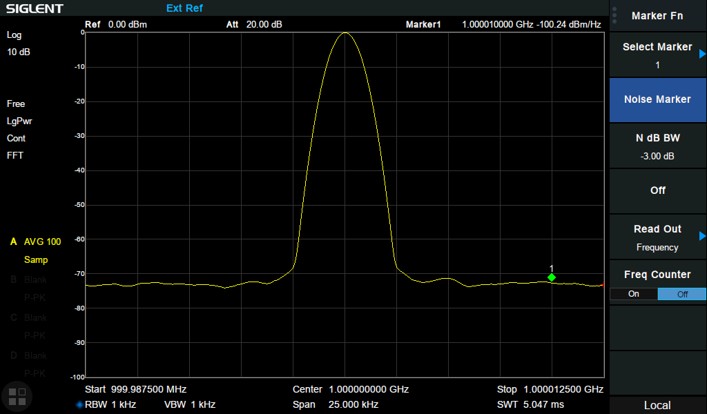
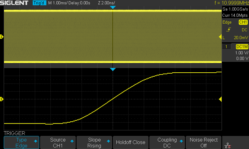
USB 3.1 Protocol Decode Software offers protocol decoding as specified in the USB 3.1 specification. PGY-USB 3.1 Protocol decode software runs in Tektronix Oscilloscope and provides measurements for protocol decode at the click of a button. This allows engineers to quickly check for USB 3.1 compliance and flexibility to debug the failure. In addition to this, engineers can decode the command and response of USB 3.1 to debug the communication. PGY-USB 3.1 takes advantage of the digital channels of MSO and provides the decoding of USB 3.1 data lines.
Key features
The configuration panel enables the user to load the Tx and Rx signals.
The tabular view displays TPeriod, TRepeat, and TBurst values in LFPS mode for Logic 1 & 0.
The tree view gives the LFPS type and timing-related values of each Logic one and 0 of the LFPS type.
The invert option has been given in case the waveform that was captured is inverted.
After the waveform has been analyzed, the results are displayed by differentiating it into Datablock and ControlBlock.
Both the scrambled bytes that have been captured and their unscrambled value is displayed in the software.
The Detail View window gives details of the bytes in each data block/control block as well as the time at which the packet has been captured.
The waveform plot is linked with the packet being displayed on the grid.
The plot contains various features like bus diagram, zoom, pan, representation of bits on the waveform, and cursors.
USB 3.0 Protocol Decode Software offers protocol decoding as specified in the USB 3.0 specification. PGY-USB 3.0 Protocol decode software runs in Tektronix Oscilloscope and provides measurements for protocol decode at the click of a button. This allows engineers to quickly check for USB 3.0 compliance and flexibility to debug the failure. In addition to this, engineers can decode the command and response of USB 3.0 to debug the communication. PGY-USB 3.0 takes advantage of the digital channels of MSO and provides the decoding of USB 3.0 data lines.
Key features
The configuration panel enables the user to load the Tx and Rx signals.
The LFPS packets are displayed in a tabular manner and give details of their timing parameters.
Under the SuperSpeed selection, the transactions are packetized to USB3.0 packets and displayed.
On expanding each packet, details with respect to that packet are displayed.
The Protocol View displays the transactions on both the Tx and Rx. This helps in the easy linking of transactions between Tx and Rx.
The Detail View window gives a comprehensive detail of the signals being analyzed.
It gives details of the bytes in each packet and the timestamp at which the packet is received.
The waveform plot is linked with the packet being displayed on the grid.
The plot contains various features like bus diagram, zoom, pan, representation of bits on the waveform, and cursors.
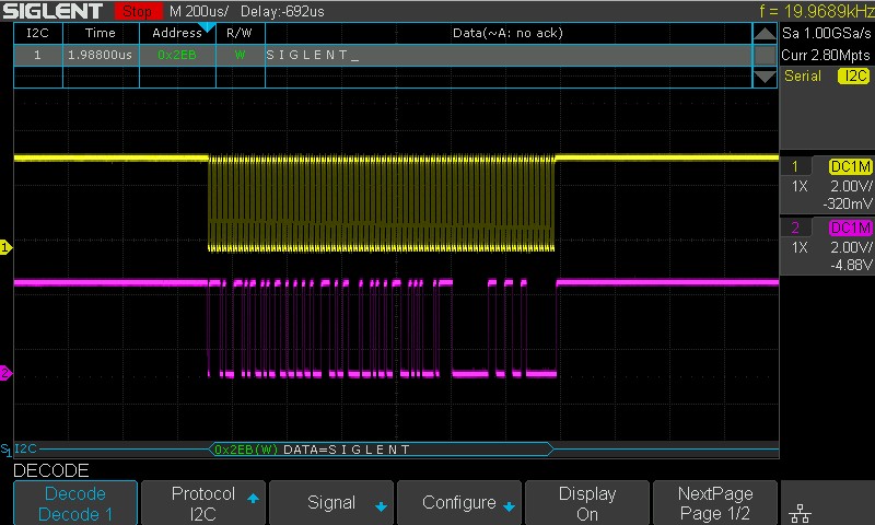
USB2.0 Protocol Decode Software offers protocol decoding as specified in the USB2.0 specification. PGY-USB2.0 Protocol decode software runs in Tektronix Oscilloscope and provides measurements for protocol decode at the click of a button. This allows engineers to quickly check for USB2.0 compliance and flexibility to debug the failure. In addition to this, engineers can decode the command and response of USB2.0 to debug the communication. PGY-USB2.0 takes advantage of the digital channels of MSO and provides the decoding of USB2.0 data lines.
Key features
Decodes the low speed, full speed, and high-speed USB 2.0 signals for easy understanding of protocol between host and device
Links the protocol content to the physical layer signal in the oscilloscope for easy understanding of the electrical characteristics of the protocol
Overlays the protocol data on the analog waveform in a bus diagram wind
The USB packet selected in the decode table is zoomed in the bus diagram for easy analysis of the electrical characteristics of the USB packet
Color coding of protocol content for easy analysis
Search capabilities to locate unique events in thousands of protocol data
Ability to view the decoded protocol data in various formats such as hexadecimal, decimal, binary, octal, and ASCII.
Ability to store the USB protocol data in CSV and txt format
Utilities such as zoom, undo, and fit screen helps in debugging while correlating the protocol data to the waveform
Export and Report generation features make sharing and archival of protocol data a trivial activity.
Supports WFM and isf file formats for offline analysis.
USB-PD Power Delivery (CC) Protocol Decode Software
USB PD Protocol Decode Software offers protocol decoding as specified in the USB PD specification. PGY-USB PD Protocol decode software runs in Tektronix Oscilloscope and provides measurements for protocol decode at the click of a button. This allows engineers to quickly check for USB PD compliance and flexibility to debug the failure. In addition to this, engineers can decode the command and response of USB PD to debug the communication. PGY-USB PD takes advantage of the digital channels of MSO and provides the decoding of USB PD data lines.
Key features
PD (CC signal) protocol Analysis using oscilloscope live channel data or stored PD signals
Displays the decoded data in PD frame format
Decoding of each packet’s bit values
Detail view displays each packet info in more detail
Easily correlate PD (CC) protocol info to Vbus status
Easily correlate CC line info to USB/Displayport traffic
Timestamp for each packet
Long duration data decode support to capture more number of PD protocol transactions
Search capabilities to locate protocol event
Documentation by exporting data in CSV and TXT file format
eMMC and SD/SDIO Electrical Validation and Protocol Decode Software
eMMC and SD, SDIO Electrical Validation and Protocol Decode Software offers electrical measurements compliance testing, and protocol decoding as specified in eMMC and SD, SDIO specification. PGY-eMMC and SD, SDIO Electrical validation and Protocol decode software run in Tektronix Oscilloscope provide electrical measurements and protocol decode at the click of a button. This allows engineers quickly check for eMMC and SD, SDIO compliance, and flexibility to debug the failure. In addition to this engineers can decode the command and respond to debugging the communication. PGY-eMMC SD, SDIO takes advantage of digital channels of MSO and provides the decoding of data lines.
Key features
eMMC, SD, and SDIO electrical measurements and Protocol testing software conform to eMMC version 4.51 and 5.0 and SD version 3.01 specification
Supports SDR and DDR and Boot mode for electrical measurement and Protocol Decode
eMMC/SD/SDIO Protocol Aware Trigger features
The software automatically identifies the read and write operations using CMD and applies the electrical parameter limits accordingly.
Detail View provides efficient debugging capability by correlating the analog waveform, protocol messages, and electrical measurements for each protocol packet in a single view
Protocol View lists the protocol activities in the sequential form to assist designers to know the host and card transactions
Timestamp at the end of the command token and time stamp at beginning of the response token in Protocol View enables the designer to comply with specifications and locate any anomaly in timing between host and card
The software displays the details of command and response in Protocol View and lists the errors messages in card status for quick analysis
Supports cursor-based measurements for manual custom measurements
Ability to store the eMMC, SD, and SDIO protocol data in CSV and txt format
Utility features like zoom, undo, and fit to screen for easy maneuvering of the waveforms while debugging the cause of the problem in Detail View makes it easy to use tool
The software seamlessly integrates with Tektronix windows based oscilloscope and supports live signal analysis using live channels of the oscilloscope
Supports data analysis for long record length and more acquisition memory of oscilloscope enables analysis of protocol events for longer duration
Report generation in pdf format
Supports WFM and isf file formats of Tektronix oscilloscope for offline analysis
eMMC (4.41, 4.51, 5.0, 5.1) and SD (UHS-I) Electrical Validation and Protocol Decode Software
eMMC and SD Electrical Validation and Protocol Decode Software offers electrical measurements compliance testing and protocol decoding as specified in eMMC and SD specifications. PGY-eMMC and SD Electrical validation and Protocol decode software run in Tektronix Oscilloscope provides electrical measurements and protocol decode at the click of a button. This allows engineers quickly check for eMMC and SD compliance and flexibility to debug the failure. In addition to this engineers can decode the command and response of eMMC and SD to debug the communication. PGY-eMMC and SD take advantage of digital channels of MSO and provide the decoding of eMMC and SD data lines.
Key features
eMMC and SD (UHS-I) electrical measurements and Protocol testing software conform to eMMC version 4.51, 5.0, 5.1 and SD version 3.01 specification
Supports SDR and DDR and Boot mode for electrical measurement and Protocol Decode
eMMC/SD/SDIO Protocol Aware Trigger features
The software automatically identifies the read and write operations using CMD and applies the electrical parameter limits accordingly.
Detail View provides efficient debugging capability by correlating the analog waveform, protocol messages, and electrical measurements for each protocol packet in a single view
Protocol View lists the protocol activities in the sequential form to assist designers to know the host and card transactions
Timestamp at the end of the command token and time stamp at beginning of the response token in Protocol View enables the designer to comply with specifications and locate any anomaly in timing between host and card
The software displays the details of command and response in Protocol View and lists the errors messages in card status for quick analysis
Supports cursor-based measurements for manual custom measurements
Ability to store the eMMC and SD protocol data in CSV and txt format
Utility features like zoom, undo, and fit to screen for easy maneuvering of the waveforms while debugging the cause of the problem in Detail View makes it easy to use tool
The software seamlessly integrates with Tektronix windows based oscilloscope and supports live signal analysis using live channels of the oscilloscope
Supports data analysis for long record length and more acquisition memory of oscilloscope enables analysis of protocol events for longer duration
Report generation in pdf format
Supports WFM and isf file formats of Tektronix oscilloscope for offline analysis
QSPI Electrical Validation and Protocol Decode Software
QSPI Electrical Validation and Protocol Decode Software offers electrical measurements compliance testing and protocol decoding as specified in QSPI specification. PGY-QSPI Electrical validation and Protocol decode software runs in Tektronix Oscilloscope and provides electrical measurements and protocol decode at the click of a button. This allows engineers quickly check for QSPI compliance and flexibility to debug the failure. In addition to this engineer can decode the command and response of QSPI to debug the communication. PGY-QSPI takes advantage of digital channels of MSO and provides the decoding of QSPI data lines.
Key features
Single and Dual Transfer rate (STR/DTR)
Supports electrical measurements and compliance testing for Ext SPI, Dual SPI and Quad SPI
Supports Triggering on command index and on S# falling edge
Supports Analog and Digital Channels of Tektronix MSO
Automated electrical measurements with customizable reference level of QSPI electrical signal
Customizable measurement limit setup for pass/fail validation of electrical signal to enable measurements
Ability to store the QSPI protocol data and electrical data in CSV and txt format
The PGY-PCIeGen3/4/5 -PA is a PCIe Protocol Analyzer that supports protocol analysis up to PCIe Gen5 speeds. PCIe design and test engineers can easily captures and record traces at 2.5, 5.0, 8, 16 and 32GT/s at specific event and obtain error report instantaneously at affordable price. This enables the design and test engineers to reduce the development time and address the time to market needs. PCIe data is captured using interposers between the root complex and end point (Device under test). PCIe Gen3/4/5 Protocol Analyzer’s software provides complete decode and error analysis of Transaction Layer Packets (TLPs), Data Link Layer Packets (DLLPs) and with LTSSM information.
Key features
PCIe Gen1/2/3/4/5-X4/8 Protocol Decode and Analysis.
Currently supports four/eight lane PCIeGen1/2/3/4/5 Bus.
M2/U.2/CEM/E1.S/SD Express interposer for speeds up to PCIe Gen5 is standard offering with protocol analyzer.
NVME Protocol Decode Capabilities
Optional solder down probe tips for four lanes for speeds up to PCIe Gen3 (8Gbps)
Protocol Decoding of TS1, TS2, TLP, DLLP Packets.
Hardware based protocol packet (TS1, TS2 and IDLE) filter capabilities.
Software based search, filter-in and filter-out capabilities.
Hardware based protocol aware trigger capabilities based on TS1, TS2, TLP and DLLP packet contents.
Advanced multi-level if-then-else if trigger capabilities.
Standard buffer size of 16GB and expandable to 64GB combined for TX and RX.
Detailed view of each TLP/DLLP with all field values.
LTSSM Analysis for PCIe protocol traffic.
Memory segmentation with each segment with different trigger condition
Trigger out signal at trigger event allows the triggering of other instruments such as an oscilloscope.
Interface to host system using USB 3.0.
Decoded data packets can be exported to .txt file for further analysis.
PGY Protocol Analyzer is light weight and can be deployed for on-site/ field tests.
Field upgradeable to enable easy maintenance and remote firmware upgrade to latest feature set.
UFS Protocol Decode Software offers protocol decoding as specified in the UFS specification. PGY-UFS Protocol decode software runs in Tektronix Oscilloscope and provides measurements for protocol decode at the click of a button. This allows engineers to quickly check for UFS compliance and flexibility to debug the failure. In addition to this, engineers can decode the command and response of UFS to debug the communication. PGY-UFS takes advantage of the digital channels of MSO and provides the decoding of UFS data lines.
Key features
UniPro and LLI Protocol Decoder enable faster system level protocol debugging
Conforms to UniPro Protocol Specification version 1.6and LLI Protocol version 1.0
Conforms to UFS Protocol Specification Version 2.0
Supports NRZ (Non-Return-to-Zero) and PWM (Pulse Width Modulation) signaling schemes
Configurable four-lane simultaneous protocol decode helps to correlate the lane to lane events
Autolink of decoded data from list table to oscilloscope waveform for easy protocol debug at PHY layer
Powerful UniPRO/LLI Protocol aware trigger features using Option ST6G serial trigger feature of oscilloscopes
Triggering supports PWM, NRZ and 8b/10B encoded data schemes
Detail view provides a comprehensive protocol and physical layer data correlation
Frame listing and frame description provide comprehensive protocol layer information
Each frame is displayed in detail as per UniPro and LLI Standard specification document
Automated CRC computation to monitor CRC errors in the protocol packet
Markers enable time measurement between messages in different lanes
The software automatically identifies the signaling scheme and gear for hassle-free protocol analysis
Bus diagram functions such as zoom, un-zoom, pan, fit to screen, and synchronize functions enable easy data analysis
Supports oscilloscope live channels, Tektronix .wfm waveform files
Generates comprehensive and customizable reports
Ability to export the protocol details to txt and CSV file formats
MDIO Protocol Analyzer and Exerciser (PGY-MDIO-EX-PD) is the Protocol Analyzer with multiple features to capture and debug communication between the host and the design under test. PGY-MDIO-EX-PD is the leading instrument that enables the design and test engineers to test the respective MDIO designs for their specifications by configuring the PGY-MDIO-EX-PD as Master/Slave, generating MDIO traffic and decoding the MDIO protocol decode packets.
MDIO also called Management Data Input/Output, or MDIO, is a 2-wire serial bus that is used to manage physical layer devices in media access controllers (MACs) in Gigabit Ethernet equipment. The management of these PHYs is based on the access and modification of their various registers.
Key features
Supports MDIO speeds of up to 25MHz
Ability to configure it as Master or Slave
Simultaneously generate MDIO traffic and Protocol decode of the Bus
MDIO Master and Slaves
Support for MDIO Clause 22 & 45
Variable MDIO data speeds and Duty cycle
Continuous streaming of protocol data to the host computer to provide a large buffer
A timing diagram of Protocol decoded bus
Listing view of Protocol activity
Ability to write exerciser script to combine multiple data frame generation at different data speeds
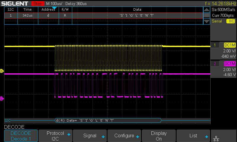
I2C/SPI Protocol Analyzer and Exerciser (PGY-I2C/SPI-EX-PD) the Protocol Analyzer with multiple features to capture and debug communication between the host and design under test. PGY-I2C/SPI-EX-PD is the leading instrument that enables the design and test engineers to test the respective I2C or SPI designs for their specifications by configuring the PGY-I2C/SPI-EX-PD as Master/Slave, generating I2C/SPI traffic and decoding the I2C/SPI protocol decode packets.
I2C is a two-wire interface to connect low-speed devices like microcontrollers, EEPROMs, A/D & D/A converters, I/O interfaces, and other small peripherals in embedded systems. The I2C bus is used by many ICs and is simple to implement. Any microcontroller can communicate with I2C buses. I2C buses can communicate on slow devices and can also use high-speed modes to transfer large amounts of data.
SPI is one of the widely used interfaces between micro-controller and peripheral ICs such as sensors, ADCs, DACs, shift registers, SRAM, and others. SPI is a synchronous, full-duplex master-slave-based interface. Both master and slave can transmit data at the same time. The SPI interface can be a 3-wire or 4-wire.
PGY-I2C/SPI-EX-PD is the leading instrument that enables the design and test engineers to test the respective I2C or SPI designs for their specifications by configuring PGY-I2C/SPI-EX-PD as master/slave, generating I2C/SPI traffic and decoding I2C/SPI Protocol decode packets.
Key features
Supports I2C Specifications
Supports SPI Specifications
Ability to configure it as Master/Slave
Generate different I2C/SPI Packets
Variable data speeds
Generate I2C/SPI traffic and protocol decode of the bus
A timing diagram of the protocol decoded bus
Listing view of protocol activity
Ability to write exerciser script to combine multiple frame generation at different data speeds
USB 2/3 host computer interface
Continuous streaming of protocol activity to host system HDD/SSD
UART Protocol Analyzer (PGY-UART-EX-PD) is the Protocol Analyzer with multiple features to capture and debug communication between the host and the design under test. PGY-UART-EX-PD is the leading instrument that enables the design and test engineers to test the respective UART designs for its specifications by configuring the PGY-UART-EX-PD as Master/Slave, generating UART traffic and decoding the UART protocol decode packets.
UART stands for Universal Asynchronous Receiver Transmitter. A UART’s main purpose is to transmit and receive serial data. PGY-UART-EX-PD is the leading instrument that enables the design and test engineers to test the UART designs for its specifications. Generating UART traffic with custom traffic capability and decoding UART Protocol packets.
Key features
Supports custom UART traffic generation
Simultaneously generate UART traffic and Protocol decode of the bus
Variable UART baud rates
Continuous streaming of protocol data to the host computer to provide a large buffer
A timing diagram of the Protocol decoded bus
Listing view of Protocol activity
Error Analysis in Protocol Decode
Ability to write exerciser script to combine multiple data frame generation at different data speeds
RFFE Protocol Analyzer (PGY-RFFE-EX-PD) is the Protocol Analyzer with multiple features to capture and debug communication between the host and design under test. The RF Front-end control interface (RFFE) Serial bus interface is emerging as a chosen for controlling RF frond-end devices. There is a variety of front-end devices such as Power Amplifiers (PA), Low-Nose Amplifiers (LNA), filters, switches, power management modules, and antenna tuners. It is widely used in mobile devices.
PGY-RFFE-EX-PD is the leading instrument that enables the design and test engineers to test the RFFE interface for its specifications by configuring PGY-RFFE-EX-PD as master/slave, generating RFFE traffic with error injection capability, amplitude variation, and decoding RFFE Protocol decode packets.
Key features
Supports RFFE2.0/2.1 Specification
Ability to configure it as Master or Slave
Generate different RFFE at full speed and half of full frequency speed
Error Injection such as parity errors and ACK/NACK errors
Variable RFFE data speeds
Simultaneously generate RFFE traffic and Protocol decode of the Bus
Timing diagram of Protocol decoded bus
Listing view of Protocol activity
Error Analysis in Protocol Decode
Ability to write exerciser script to combine multiple data frame generation at different data speeds
USB2/3 host computer interface
Flexibility to upgrade to the unit for evolving RFFE Specification
I3C Protocol Analyzer (PGY-I3C-EX-PD) is the Protocol Analyzer with multiple features to capture and debug communication between host and design under test. I3C Serial bus interface is emerging as a chosen interface for all future sensor connectivity in mobile phone and automotive industries. This could also be chosen as a low-cost, reliable interface for future embedded electronic applications to address the new data-intensive applications.
The PGY-I3C-EX-PD is the leading instrument that enables the design and test engineers to test the I3C designs for their specifications by configuring the PGY-I3C-EX-PD as Master/Slave to generate I3C traffic with error injection capabilities and to decode I3C protocol packets.
Key features
Supports v1.0/v1.1/v1.1.1 Specifications*.
Ability to configure it as Master and/or Slave.
Ability to configure BCR, LVR, and DCR registers.
Simultaneously generate I3C traffic and Protocol decode of the Bus.
Optional Compliance Test Specifications (CTS) test script support.
Optional support of MCTP Protocol Exerciser and Analyzer over I3C for advanced management and control protocol analysis. View application note[here].
Supports legacy I2C slaves and masters.
Generate different I3C SDR and HDR Packets.
Supports IBI and Hot Plug capabilities.
Error Injection such as CRC errors, parity errors, and ACK/NACK errors.
Variable I3C data speeds and duty cycle.
PMIC device support as per JEDEC DDR5 spec requirement.
Margin test capability: Voltage and timing variation.
Continuous streaming of protocol data between the instrument and host computer.
Timing diagram of Protocol decoded bus.
Listing view of Protocol activity.
Error Analysis in Protocol Decode.
Ability to write exerciser script to combine multiple data frame generation at different data speeds.
UHS-II Protocol Analyzer (PGY-UHS-II SD/SDIO) is the Protocol Analyzer with multiple features to capture and debug communication between the host and design under test. PGY-UHS-II SD/SDIO UHS-II Protocol Analyzer is the most feature-rich comprehensive Protocol Analyzer available to capture and debug UHS-II protocol data. PGY-UHS-II Protocol Analyzer supports FD156 and HD312 data rates. The innovative active probe has minimum electrical loading on the device under test (DUT) and captures protocol data without affecting the performance of the DUT.
PGY-UHS-II SD/SDIO UHS-II Protocol Analyzer is the most feature-rich comprehensive Protocol Analyzer available to capture and debug UHS-II protocol data. PGY-UHS-II Protocol Analyzer supports FD156 and HD312 data rates. The innovative active probe has minimum electrical loading on the device under test (DUT) and captures protocol data without affecting the performance of the DUT. PGY-UHS-II protocol analyzer allows streaming of protocol data from PGY-UHS-II Protocol Analyzer to the host system (using USB 3.0 or GbE interface). Comprehensive decoding of data, protocol tests, and error analysis enables verification of the communication between the UHS-II host and device.
PGY-UHS-II Protocol Analyzer allows Design and Test Engineers to test and debug SD UHS-II Interface triggering on command, response, data, or CRC errors. PGY-UHS-II Protocol analyzer instantaneously provides decoding of CCMD, DCMD, MSG, DATA, and its arguments. The Analytics feature offers a graphical representation of command, response, data, and frequency of operation for the acquired duration.
Key features
Continuous monitoring and streaming of protocol data to capture exclusive events (more than 30GB data capture)
Protocol tests of captured data for protocol integrity, DCMD, CCMD, MSG, and DATA
Instantaneous display of Protocol activity while the PGY-UHS-II is capturing the Protocol data allowing almost live analysis of protocol activity
Hardware-based protocol-aware trigger capability enables capturing specific events
Trigger on CRC error conditions allows capturing infrequent error events
Users can identify the anomalies by decoding the command and response argument
Analytics provides analysis of acquired protocol data by plotting command, response, data, and frequency of operation over acquired time
Decoding of device registers for easy analysis
The filter feature allows you to view specific packets in decoded protocol packets
Search for specific events in protocol activity
Easy-to-use software user interfaces reduces the learning curve of protocol analysis
Software is designed to handle long-duration capture and display of the decoded data without demanding extensive resources in the host computer
Insertion of markers in protocol activity helps in correlating the input digital signal with Protocol Activity
Trigger out a signal for any specific protocol event allows the triggering of other instruments such as an oscilloscope
Interface to host system using USB3.0 or Gigabit Ethernet interface
Flexibility to upgrade the hardware firmware using the GbE interface provides easy field up-gradation of firmware
Decoded data packets can be exported to CSV file for further analysis
QSPI Protocol Analyzer (PGY-QSPI-EX-PD) is the Protocol Analyzer with multiple features to capture and debug communication between the host and design under test. PGY-QSPI-EX-PD is the leading instrument that enables the design and test engineers to test the respective QSPI designs for their specifications by configuring the PGY-QSPI-EX-PD as Master/Slave, generating QSPI traffic, and decoding the QSPI protocol decode packets.
PGY-QSPI-EX-PD is the leading instrument that enables the design and test engineers to test the QSPI designs for its specifications by configuring PGY-QSPI-EX-PD as master/slave, generating QSPI traffic with error injection capability and decoding QSPI Protocol packets.
Key features
Supports QSPI speeds of up to 80MHz
Ability to configure it as Master or Slave
Simultaneously generate QSPI traffic and Protocol decode of the Bus
QSPI Master and Slaves
STR and DTR Transfer rates
Extended, Dual, and Quad QSPI Modes Supported
Variable QSPI data speeds and duty cycle
Continuous streaming of protocol data to the host computer to provide a large buffer
A timing diagram of Protocol decoded bus
Listing view of Protocol activity
Error Analysis in Protocol Decode
Ability to write exerciser script to combine multiple data frame generation at different data speeds
eMMC/SD Tester is a dedicated industry’s first eMMC/SD card tester-based system on chip (SOC). Users can write different protocol tests for eMMC4.41/4.51/5.0 and 5.1 (HS400) and SD3.0 (UHS-I) to test for protocol specifications.
PGY-eMMC/SD-Tester card provides the flexibility to write custom test cases based on different used cases and extensively test the eMMC devices and SD card to ensure reliability of the devices to meet different used cases.
Key features
Design and run custom test cases tests for eMMC 4.41, 4.51, 5.0, and 5.1 (HS400), and SD 3.0 (UHS-I) to validate protocol specifications.
SoC-Based Testing with Embedded OS: Control the tester via PC with Windows and Linux compatibility, and benefit from embedded SPI flash booting, ensuring complete device access from initialization.
Compatible with eMMC 4.41, 4.51, 5.0, and 5.1 (HS400).
Supports SD 3.0 (UHS-I)
Host emulation for realistic testing scenarios.
Host Connection via USB 3.0 or 1 GbE Ethernet.
Comprehensive support for all eMMC and SD commands
PGY-SSM-EV-Tester is an AC/DC characterization platform that provides flexibility to make AC/DC measurements of eMMC, SD, and MicroSD devices at different operating modes enabling the validation engineers to do in-depth automated electrical and timing performance analysis to ascertain the endurance and reliability of eMMC and SD devices. This test solution saves significant test time and reduces human errors.
PGY-SSM-EV-Tester eMMC and SD AC/DC Electrical Validation platform provide comprehensive electrical validation data to characterize eMMC devices for eMMC 4.41, 4.51, 5.0, and 5.1 (HS400) and SD 2.0/3.0 specifications. This innovative solution enables the validation engineers to run test cases to test different specifications and make all electrical parametric measurements. It covers 100s of measurements which could be completed in an hour instead of spending days.
Key features
Measures AC/DC Electrical Measurements as per eMMC 4.41, 4.51, 5.0 and 5.1 Specification.
Measures AC/DC Electrical measurements as per SD 2.0/3.0(UHS-I) Specification.
Standard test cases to make measurements at different data rates.
Flexibility to test the device for min and max limits of the specification.
Tolerance testing of devices outside the limits.
Statistical measurements to enhance the reliable of measurements.
Powerful debugging capabilities of AC/DC measurements in oscilloscope waveform.
Protocol Decoding of Command Signal and Data blocks of acquired with CRC check.
Upgradable to Protocol Analysis.
Flexibility to vary the clock, CMD and data signals timing parameters.
SD, SDIO, eMMC Protocol Analyzer (PGY-SSM) is the Protocol Analyzer with multiple features to capture and debug communication between the host and design under test. SD, SDIO, and eMMC Protocol Analyzer support SD, SDIO, and eMMC for data rates up to 200MHz (HS400) DDR mode. SD, SDIO, and eMMC Protocol Analyzer is the industry’s first eMMC protocol analyzer that supports version 4.41, 4.51, 5.0, and 5.1 specifications.
The innovative active probe has minimum electrical loading on the device under test (DUT) and allows protocol data capture without affecting the performance of the DUT. In an industry-first feature, the PGY-SSM protocol analyzer allows continuous streaming of protocol data from the PGY-SSM Protocol Analyzer to the host system (using USB 3.0 or GbE interface) running the UI. Comprehensive decoding of protocol data, command units, and real-time error analysis enables effective verification of communication of SD/SDIO/eMMC host and device.
PGY-SSM Protocol Analyzer enables design and verification engineers to test and debug SD, SDIO, and eMMC by triggering command, response, data, or CRC errors. It also provides instantaneous decoding of Command, Response, CID, CSD, and Ext CSD registers. The Analytics feature offers an easy analysis of the graphical representation of command, response, data, and frequency of operation for the acquired duration.
Key features
Continuous monitoring of protocol data for a long time to capture elusive events (more than 30GB data capture)
Analysis of captured data per standards for protocol integrity, count of data bursts, CMD CRC errors, Response CRC errors, Data CRC errors, Timing Values, and Reserved commands
Hardware-based protocol-aware trigger capability in real-time enables capturing specific Events. Triggering facility on patterns, commands, or error events.
Users can identify the anomalies by decoding command and response arguments
Analytics feature provides analysis of acquired protocol data by plotting command, response, data, and frequency of operation over acquired time
The analytics feature also provides the decoding of device registers for easy analysis
Filters allow you to view specific packets in decoded protocol packets
Search feature for specific events in protocol activity
Easy-to-use user interfaces save time on the learning curve
Handles long-duration capture and displays the decoded data without demanding extensive resources in the host computer
Inserting markers [using Trigger-In] in protocol activity helps in correlating the input digital signal with Protocol Activity
Trigger-out signal for any specific protocol event allows triggering of other instruments such as oscilloscope
Interface to host system [running UI] using USB3.0 or Gigabit Ethernet interface
Flexibility to upgrade the hardware firmware using the GbE interface provides easy field up-gradation of firmware
Export of Decoded data packets to a txt file for further analysis.
The UFS Test Board is designed to issue SCSI commands, query requests for attributes, flags, and descriptors, as well as execute UIC commands. This setup serves as a powerful UFS device test environment, enabling in-depth analysis and verification. This high-performance analyzer confirms the UFS traffic and provides critical insights into the UFS device’s operations.
Key features
Issue SCSCI commands
Query request commands for attributes, flags and descriptors.
DME/UIC commands
Power mode change commands for setting gears (HS 1,2,3,4), rate(A, B), lane(1, 2), power mode(fast and fast auto)
UFS Protocol Analyzer (PGY-UFS3.X-PA) is the Protocol Analyzer with multiple features to capture and debug communication between the host and design under test. PGY-UFS3.X-PA, UFS Protocol Analyzer, a value-based analyzer in its class, offers capture and debugging of data across MPHY, UniPro, and UFS protocol layers. It allows for instantaneous decoding of the UFS layer, UniPro layer, and MPHY layer with the flexibility to correlate decoded data across these protocol layers.
PGY-UFS3.X-PA Supports PWMG1 to HSG4B data rates and two TX, and two RX lane decode. The active probe has minimum electrical loading on the device under test (DUT) and captures protocol data without affecting the performance of the DUT. PGY-UFS3.X-PA protocol Analyzer can support two-lane data. Comprehensive decoding UniPro & UFS on the Fly enables validation of communication between host and device.
PGY-UFS3.X-PA, UFS Protocol Analyzer allows Design and Test Engineers to obtain deep insight into UFS host and device communication. MPHY/UniPro/UFS packet-based triggering allows specific protocol data capture and analysis. PGY-UFS3.X-PA Protocol analyzer instantaneously provides decoding of the UFS layer, UniPro layer, and MPHY layer with a correlation to MPHY, UniPro, and UFS layer.
Key features
Supports version MPHY 4.0, UniPro 1.8, and UFS version 2.1/3.1
Supports PWM G1 to G7 and HS G1, 2, 3, 4 A and B Series · Supports one/two data lanes (2 TX and 2 RX)
Flexibility to capture very large data using continuous streaming of Protocol data to host computer
Hardware-based circular buffer
Flexibility to decode selected data from an 8GB buffer
Solder down active probe provides high signal fidelity
Decoding at MPHY, UniPro, and UFS layer
Trigger-based on MPHY, UniPro, and UFS layer packet content
Supports triggering in PWM and HS data rate speeds
Trigger out a signal at the trigger event allows the triggering of other instruments such as an oscilloscope
Interface to host system using USB 3.0 or Gigabit Ethernet Interface
Flexibility to upgrade the hardware firmware using the GbE interface provides easy field up-gradation of FPGA firmware
Decoded data packets can be exported to a text file for further analysis
PGY-UFS 3.0-PA Protocol Analyzer is lightweight and can be deployed for on-site/ field tests
UFS 4.0 Protocol Analyzer (PGY-UFS4.0-PA) is the Protocol Analyzer with multiple features to capture and debug communication between the host and design under test (DUT). PGY-UFS4.0-PA, UFS Protocol Analyzer, a value-based analyzer in its class, offers capture and debugging of data across MPHY, UniPro, and UFS protocol layers. It allows for instantaneous decoding of the UFS layer, UniPro layer, and MPHY layer with the flexibility to correlate decoded data across these protocol layers.
PGY-UFS4.0-PA, UFS Protocol Analyzer is the industry-first working and tested UFS4.0 Protocol Analyzer. It offers protocol data capture and debugging of data across MPHY, UniPro, and UFS protocol layers. It allows for instantaneous decoding of UFS, UniPro, and MPHY layers with the flexibility to correlate decoded data across these protocol layers. PGY-UFS4.0-PA supports PWMG1 to HSG5B data rates and two TX, and two RX lane decode. The active probe has minimum electrical loading on the device under test (DUT) and captures protocol data without affecting the performance of the device under test (DUT). PGY-UFS4.0- PA Protocol Analyzer supports two-lane data. Comprehensive on the fly decoding of UniPro & UFS data enables validation of communication between UFS host and device.
PGY-UFS4.0-PA Protocol Analyzer allows Design and Test Engineers to gain deep insight into UFS host and device communication. MPHY/UniPRO/UFS packet-based triggering allows specific protocol data capture and analysis. PGY-UFS Protocol analyzer instantaneously provides decoding of UFS, UniPro, and MPHY layers with a correlation to MPHY, UniPro, and UFS layers.
Key features
Supports version MPHY 5.0, UniPro 2.0, and UFS v2.1/3.1/4.0
Supports PWM G1 to G7 and HS G1, 2, 3, 4, 5 Rate A and B Series
Supports one/two data lanes (2 TX and 2 RX)
Flexibility to capture very large data using continuous streaming of Protocol data to host computer with 16GB Internal acquisition memory field upgradeable up to 64GB.
Hardware-based resizable circular buffer with pre/post-trigger.
Flexibility to decode selected data from a 16GB buffer.
Solder down active probe provides high signal fidelity.
Decoding at MPHY, UniPro, and UFS layers.
Trigger-based on MPHY, UniPro, and UFS layers packet content.
Trigger out a signal at the trigger event allows the triggering of other instruments such as an oscilloscope.
Interface to host system using USB 3.0.
Flexibility to upgrade the hardware firmware using the GbE interface provides easy field up-gradation of FPGA firmware.
Decoded data packets can be exported to a text file for further analysis.
Lightweight and can be deployed for on-site/ field tests.
Standard OCXO and step attenuator (0 to 110 dB, 10dB step)
Pulse modulation and pulse train generator (option)
Product Overview
In order to develop, test and optimize these more complex systems, the measurement technology must exceed the desired system performance. The SSG6000A is designed to provide high performance signal quality that meets the stringent requirements of the latest microwave and millimeter wave testing while extending customer value in size, speed, and cost.
SSG6000A Series RF Signal Generator supports AM and pulse modulation, pulse sequence generator, power meter control and other functions. With standard OCXO reference hardware module inside ensures high-precision and high stability signal output. It is not only an ideal local oscillator and clock source, but also a high-performance analog signal source suitable for applications in R&D and production. SIGLENT provides a total solution backed by proven reliability and our standard 3 years warranty plus pre-sale and post-sale support. Coupled with solid RF performance, a flexible and pure signal, the SSG6000A is a complete solution that makes a great addition to any RF engineer’s workbench kit.
Tracking generator (TG) is currently included at no charge
Product Overview
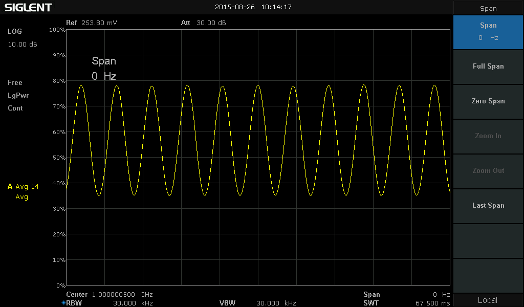
Siglent SSA3000X Spectrum Analyzers offer a frequency range of 9 KHz to 2.1/3.2 GHz. With their light weight, small size, and friendly user interface, the SSA3000X present a large, bright, easy to read display, powerful and reliable automatic measurements, and plenty of impressive features.
SSA3000X Spectrum Analyzers’ applications include research and development, education, production, maintenance, and pre-compliance testing.
Key Features
Standard Preamplifier
Standard Tracking Generator Kit (Included)
Reflection/VSWR Measurement Kit (Opt.*)
Advanced Measurement Kit/Waterfall Chart (Opt.*)
EMI Pre-compliance Measurements Kit (Opt.*)
10.1 lnch WVGA (1024 x 600) Display
*New SSA3000X analyzers feature approximately 40 hours of free trials of these options. The trial timer is running when the instrument is powered on. After the trial has expired, the function will be disabled/greyed out.
Product Characteristics
Easy to operate, Support four independent traces and cursors
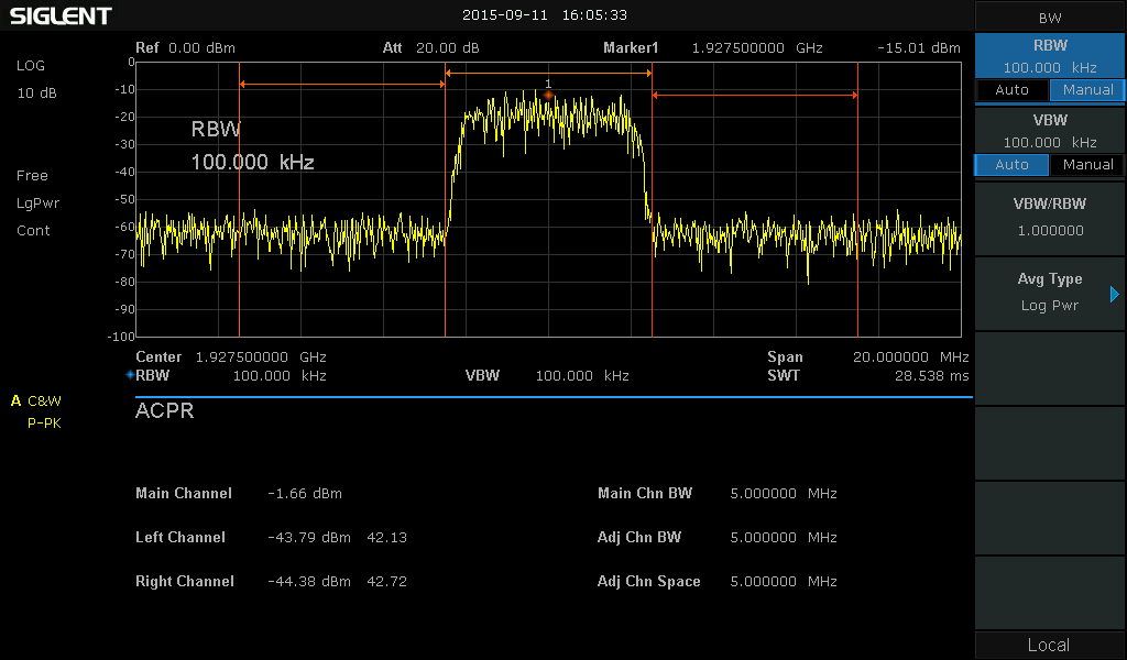
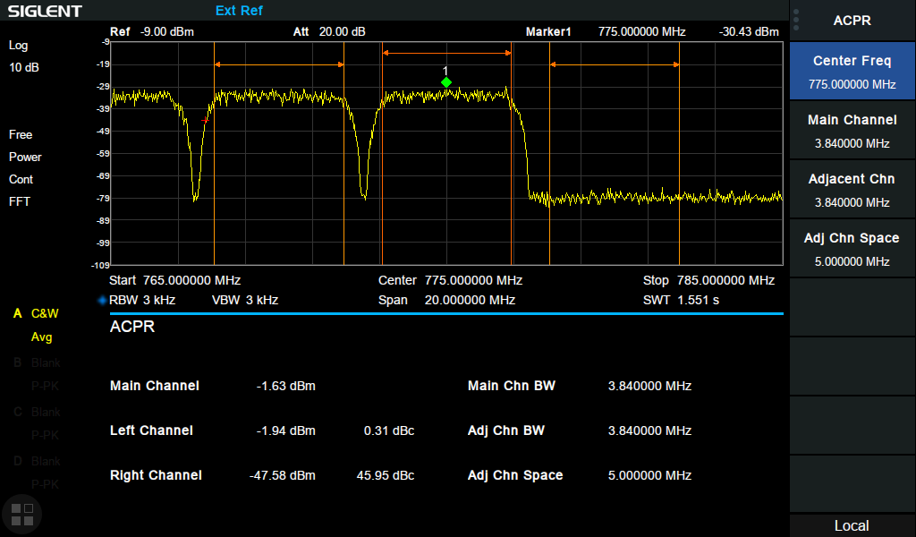
Channel power, ACPR, Harmonics, and TOI measurement option
Standard preamplifier, 8.4” touch screen, 4 hours working time
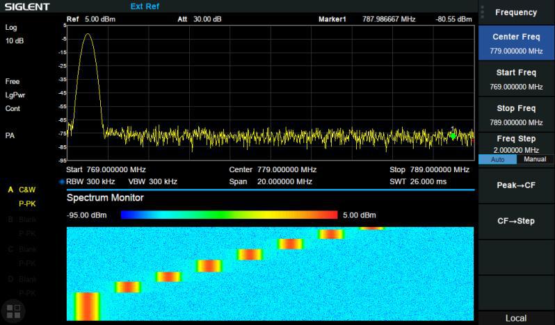
GPS location and logging
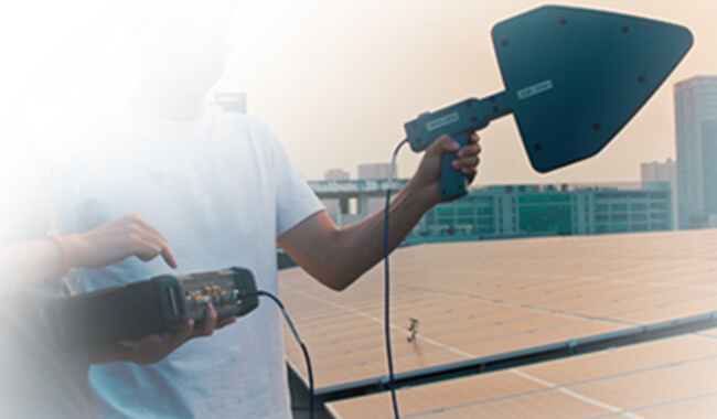
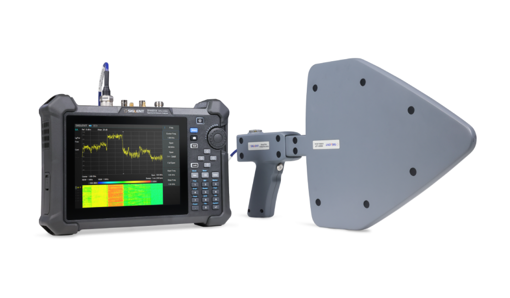
Product Overview
SIGLENT SHA850A, a handheld portable spectrum analyzer and cable-and-antenna analyzer, is a powerful and flexible tool for those field and outdoor RF applications.
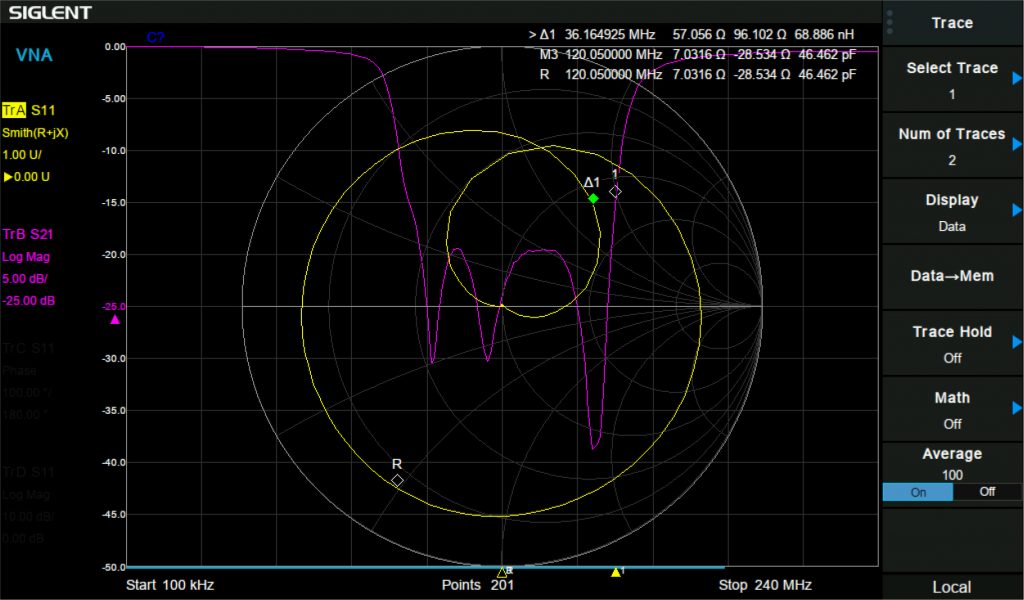
With a frequency range up to 7.5 GHz, the analyzer delivers reliable automatic measurements and multiple modes of operation. A spectrum analyzer, including built-in amplifier and independent signal source, fast scanning speed, high sensitivity, can achieve broadcast monitoring, channel power scanning, wireless interference location, power monitoring, electromagnetic compatibility, and other functions. A cable and antenna tester including built-in DC voltage bias, with a 1-path-2-port vector network analysis function, can measure TDR, VSWR, port matching debugging, insertion loss measurement, tower amplifier debugging, cable fault location, Smith chart, etc.
Frequency Range
Resolution Bandwidth (RBW)
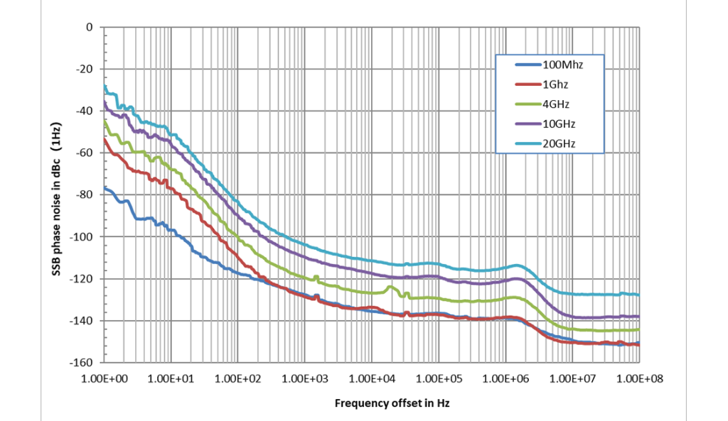
Phase Noise
Total Amplitude Accuracy
Display Average Noise Level (DANL)
SHA851A
9 kHz~3.6 GHz
1 Hz ~ 3 MHz, in 1-3-10 sequence
-104 dBc/Hz
±0.7 dB
-165 dBm/Hz
SHA852A
9 kHz~7.5 GHz
1 Hz ~ 3 MHz, in 1-3-10 sequence
-104 dBc/Hz
±0.7 dB
-165 dBm/Hz
Key Features
Spectrum Analyzer Frequency Range from 9 kHz up to 3.6 GHz/7.5 GHz
Cable and Antenna Test Frequency Range from 100 kHz up to 7.5 GHz, Distance To Fault and Time Domain Analysis
Vector Network Analyzer (Opt.*) Frequency Range from 100 kHz up to 7.5 GHz, Bias out up to 32VDC (Opt.*)
SIGLENT SVA1000X Spectrum and Vector Network Analyzers are powerful and flexible tools for RF signal and network analysis. With a frequency range to 7.5 GHz, the SVA1000X analyzer delivers reliable automatic measurements and multiple modes of operation: the base model is a spectrum analyzer and a vector network analyzer, and optional functions include a distance-to-fault locator, and a vector signal modulation analyzer.
SVA1000X Spectrum and Vector Network Analyzers’ applications include broadcast monitoring/evaluation, site surveying, S-parameter measurement, cable and antenna testing, analog/digital modulation analysis, EMI pre-compliance test, research and development, education, production, and maintenance.
Frequency Range
Resolution Bandwidth (RBW)
Phase Noise
Total Amplitude Accuracy
Display Average Noise Level (DANL)
SVA1015X
9 kHz to 1.5 GHz
1 Hz to 1 MHz, in 1-3-10 sequence
< -98 dBc/Hz @ 1 GHz, 10 kHz offset
≤1.2 dB
-156 dBm/Hz, Normalized to 1 Hz (typ.)
SVA1032X
9 kHz to 3.2 GHz
1 Hz to 1 MHz, in 1-3-10 sequence
< -98 dBc/Hz @ 1 GHz, 10 kHz offset
<0.7 dB
-161 dBm/Hz, Normalized to 1 Hz (typ.)
SVA1075X
9 kHz to 7.5 GHz
1 Hz~3 MHz
< -98 dBc/Hz @ 1 GHz, 10 kHz offset
<0.7 dB
-165 dBm/Hz, Normalized to 1 Hz (typ.)
Key Features
Tracking Generator Standard
Distance To Fault (Opt.*)
Vector Network Analyzer function (included after 9/23/2019)
EMI Filter and Quasi-Peak Detector Kit (Opt.*)
Advanced Measurement Kit/Waterfall chart (Opt.*)
10.1 lnch Multi-Touch Screen, Mouse and Keyboard supported
Web Browser Remote Control on PC and Mobile Terminals and File Operation
*New SVA1000X analyzers feature approximately 100 hours of free trials of these options. The trial timer is running when the instrument is powered on. After the trial has expired, the function will be disabled/greyed out.
10.1 lnch Multi-Touch Screen, Mouse and Keyboard supported
Web Browser Remote Control on PC and Mobile Terminals and File Operation
Product Overview
SIGLENT SSA3000X Plus Spectrum Analyzers are powerful and flexible tools for RF signals and network analysis. With a frequency range up to 7.5 GHz, the SSA3000X analyzers deliver reliable automatic measurements and multiple modes of operation: spectrum analyzer the base, optional functions include RF power measurement, vector signal modulation analysis, reflection measurement, and EMI test.
SSA3000X Plus Spectrum Analyzers’ applications include broadcast monitoring/evaluation, site surveying, S-parameter measurement, analog/digital modulation analysis, EMI pre-compliance test, research and development, education, production, and maintenance.
Frequency Range
Resolution Bandwidth (RBW)
Phase Noise
Total Amplitude Accuracy
Display Average Noise Level (DANL)
SSA3015X Plus
9 kHz ~ 1.5 GHz
1 Hz~1 MHz
< -99 dBc/Hz
< 1.2 dB
-156 dBm/Hz
SSA3021X Plus
9 kHz ~ 2.1 GHz
1 Hz~1 MHz
< -98 dBc/Hz
< 0.7 dB
-161 dBm/Hz
SSA3032X Plus
9 kHz~3.2 GHz
1 Hz~1 MHz
< -98 dBc/Hz
< 0.7 dB
-161 dBm/Hz
SSA3075X Plus
9 kHz~7.5 GHz
1 Hz~3 MHz
< -98 dBc/Hz
< 0.7 dB
-165 dBm/Hz
Key Features
Spectrum Analyzer Frequency Range from 9 kHz up to 1.5 GHz / 2.1 GHz / 3.2 GHz / 7.5GHz
Analog and Digital Signal Modulation Analysis Mode (Opt.*)
Reflection Measurement Kit (Opt.*)
EMI Filter and Quasi-Peak Detector Kit(Opt.*)
Advanced Measurement Kit/Waterfall chart (Opt.*)
10.1 lnch Multi-Touch Screen, Mouse and Keyboard supported
Web Browser Remote Control on PC and Mobile Terminals and File Operation
*New SSA3000X Plus instruments feature approximately 100 hours of free trials of these options. The trial timer is running when the instrument is powered on. After the trial has expired, the function will be disabled/greyed out.
Web Browser Remote Control on PC and Mobile Terminals and File Operation
Product Overview
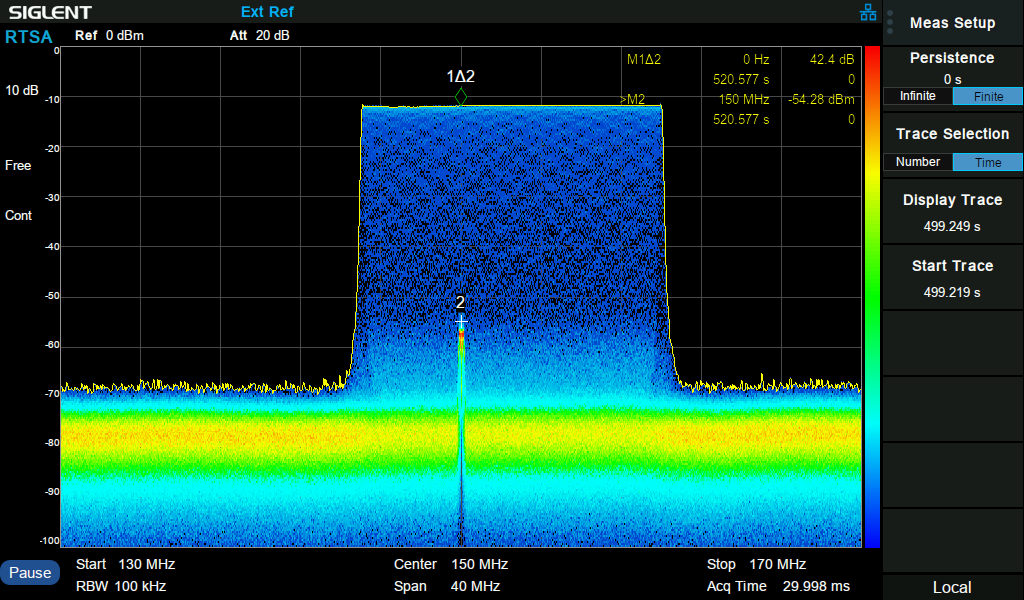
SIGLENT SSA3000X-R real-time spectrum analyzers are powerful and flexible tools for complex RF signal monitoring and analysis. With a capability of 40 MHz analysis bandwidth and 7.2 µs 100% POI, the SSA3000X-R spectrum analyzers can provide multi-dimensions data displays, advanced triggering, and RF data capturing, to solve modern RF spectrum challenges, like hopping frequency, conflict channel, spectrum interference, etc. They also provide a standard tracking generator for network analysis, optional wideband digital modulation analysis, and EMI pre-compliance test.
SSA3000X-R applications include broadcast monitoring/evaluation, cellular site, IoT, WiFi, Bluetooth surveying, research and development, education, production, and maintenance.
These powerful spectrum analyzers are even more useful with the addition of free Vector Network Analysis (VNA) and Distance-to-fault (DTF) functions included. Now, you can perform critical real-time analysis and RF device characterization with one instrument!
Frequency Range
Resolution Bandwidth (RBW)
Phase Noise
Total Amplitude Accuracy
Display Average Noise Level (DANL)
SSA3032X-R
9 kHz~3.2 GHz
1 Hz~3 MHz
<-98 dBc/Hz
< 0.7 dB
-165 dBm/Hz
SSA3050X-R
9 kHz~5.0 GHz
1 Hz~3 MHz
<-98 dBc/Hz
< 0.7 dB
-165 dBm/Hz
SSA3075X-R
9 kHz~7.5 GHz
1 Hz~3 MHz
<-98 dBc/Hz
< 0.7 dB
-165 dBm/Hz
Key Features
Spectrum Analyzer Frequency Range from 9 kHz up to 3.2 GHz / 5.0 GHz / 7.5 GHz
Analog Modulation Analysis and Vector Digital Modulation Analysis
Channel power, ACPR, OBW, Harmonics, and TOI measurement option
Web Browser for easy Remote Control over LAN
Product Overview
The SIGLENT SSA5000A spectrum analyzers are powerful and flexible tools for complex RF spectrum and signal analysis. With the capability of real-time spectrum analysis, the analyzer can provide multi-dimensions data displays, and advanced triggering to solve modern RF spectrum challenges, like channel power measurement, hopping frequency, conflict channel, and spectrum interference.
Applications include broadcast monitoring/evaluation, cellular site, IoT, WLAN and Bluetooth surveying, research and development, education, production, and maintenance.
Frequency Range
Resolution Bandwidth (RBW)
Phase Noise
Total Amplitude Accuracy
Display Average Noise Level (DANL)
SSA5083A
9 kHz~13.6 GHz
1 Hz ~ 10 MHz, in 1-3-10 sequence
<-105 dBc/Hz
<0.5 dB
-165 dBm/Hz
SSA5085A
9 kHz~26.5 GHz
1 Hz ~ 10 MHz, in 1-3-10 sequence
<-105 dBc/Hz
<0.5 dB
-165 dBm/Hz
Key Features
Spectrum Analyzer Frequency Range from 9 kHz up to 13.6 GHz/26.5 GHz
SDM3045X 4 1/2 Digits Dual-Display Digital Multimeter
Real 4½ digit (66,000 count) readings resolution
Up to 150 rdgs/s measurement speed
True-RMS AC Voltage and AC Current measuring
1 Gb NAND flash size, Mass storage configuration files and data files
Built-in cold terminal compensation for thermocouple
With easy, convenient and flexible PC software: EasyDDM
Product Overview
The SIGLENT SDM3045X Digital Multimeter is a 4½ digit (66,000 count) multimeter incorporating a dual-display and is especially well suited for the needs of high-precision, multifunction and automatic measurement applications.
Reading Resolution
DC Voltage Accuracy in a Year
DC Voltage Measurement Range
AC Voltage Measurement Range
DC Current Measurement Range
Scanner Card
SDM3045X
4 1/2
0.06% of reading + 8 counts
600 mV-1000 V
600 mV -750 V
600 µA -10 A
——
Key Features
Standard interface: USB Device, USB Host, LAN
User-friendly Design
4.3″ TFT-LCD, 480*272
Support dual display, Chinese and English Menu
Built-in front panel accessible help system
File management (support for USB Driver and local storage)
USB & LAN remote interfaces support common SCPI command set. Compatible with other popular DMMs on the market.
Not compatible with the SC1016 Scanner Card Option
SDM3055 5 ½ Digits Dual-Display Digital Multimeters
Real 5½ digits readings resolution ( 240, 000 counts )
Up to 150 rdgs/s measurement speed
True-RMS AC Voltage and AC Current measuring
1 Gb Nand flash size, Mass storage configuration files and data files
Optional Scanner for multipoint measurements (-SC part number)
Product Overview
The SDM3055 digital multimeter and SDM3055-SC digital multimeter are designed with 5 ½ digits readings resolution and dual-display, especially fitting to the needs of high-precision, multifunction and automatic measurement.
The SIGLENT SDM3055-SC includes a multiplexer that provides multi-point measurement capabilities. The scanner features 12 multi-purpose + 4 current channels and supports the following measurement functions: DCV, ACV, DCI, ACI, 2WR, 4WR, CAP, FREQ, DIODE, CONT and TEMP (RTD and Thermocouple ). It provides a convenient and versatile solution for test applications that require multiple measurement points or signals and is an ideal tool for R&D burn-in and production testing.
NOTE: The scanner is included on new SDM3055-SC products only. It cannot be added to SDM3055 instruments at a later time.
Reading Resolution
DC Voltage Accuracy in a Year
DC Voltage Measurement Range
AC Voltage Measurement Range
DC Current Measurement Range
Scanner Card
SDM3055
5 1/2
0.015% of reading + 0.003% of range
200 mV - 1000 V
200 mV - 750 V
200 µA - 10 A
No
SDM3055-SC
5 1/2
0.015% of reading + 0.003% of range
200 mV - 1000 V
200 mV - 750 V
200 µA - 10 A
Yes
Key Features
Built-in cold terminal compensation for thermocouple temperature measurements
With easy, convenient and flexible PC software: EasyDMM
Standard interfaces: USB Host, LAN ( Optional Accessories USB-GPIB Adapter )
Support remote control operation via SCPI commands. Compatible with commands of main stream multimeters
SDM3065X 6 ½ Digits Dual-Display Digital Multimeters
Real 6½ digits readings resolution (2,200,000 counts)
1 Gb Nand flash size, Mass storage configuration files and data files
True-RMS AC Voltage and AC Current measuring
Standard interfaces: USB Device, USB Host, LAN (Optional Accessories: USB-GPIB Adapter)
Optional Scanner for multipoint measurements (-SC part number)
Product Overview
SIGLENT SDM3065X and SDM3065X-SC Digital Multimeters are a 6 ½ digit DMM (digital multimeter with 2,200,000 counts) incorporating a dual–display. The SDM3065X series is especially well-suited for the needs of high-accuracy and high-precision applications measurement.
The SIGLENT SDM3065X-SC includes a multiplexer that provides multi-point measurement capabilities. The scanner features 12 multi-purpose + 4 current channels and supports the following measurement functions: DCV, ACV, DCI, ACI, 2WR, 4WR, CAP, FREQ, DIODE, CONT and TEMP ( RTD and Thermocouple ). It provides a convenient and versatile solution for test applications that require multiple measurement points or signals and is an ideal tool for R&D burn-in and production testing.
NOTE: The scanner is included on new SDM3065X-SC products only. It cannot be added to SDM3065X instruments at a later time.
Reading Resolution
DC Voltage Accuracy in a Year
DC Voltage Measurement Range
AC Voltage Measurement Range
DC Current Measurement Range
Scanner Card
SDM3065X
6 1/2
0.0035% of reading + 0.0006% of range
200 mV-1000 V
200 mV-750 V
200 µA-10 A
No
SDM3065X-SC
6 1/2
0.0035% of reading + 0.0006% of range
200 mV-1000 V
200 mV-750 V
200 µA-10 A
Yes
Key Features
Supports double display, Chinese and English Menu
File management (support for U-disc and local storage)
Built-in cold terminal compensation for thermocouple
Comes with easy, convenient and flexible any sensor measurement control software :EasyDMM
Math Function: Max, Min, Average, Standard Deviation, dBm/dB, Relative Measurement, Pass/Fail Histogram, Trend Chart, Bar Meter,etc.
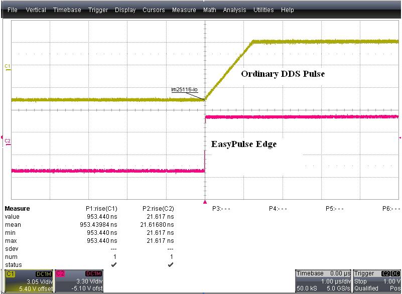
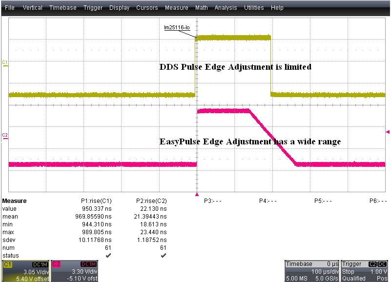
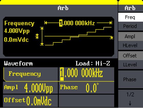
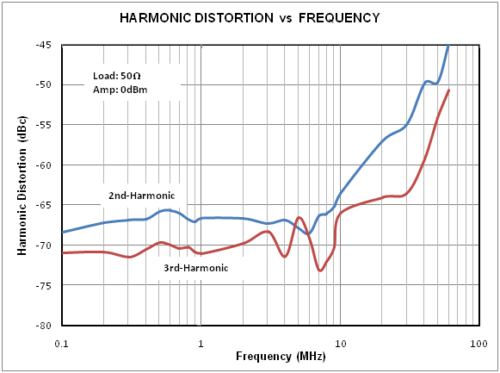
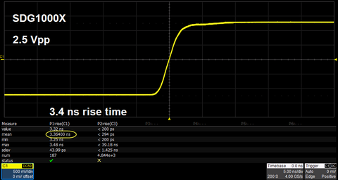
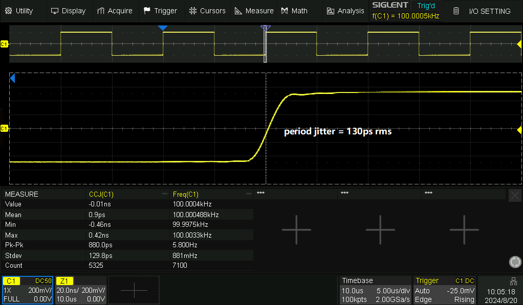
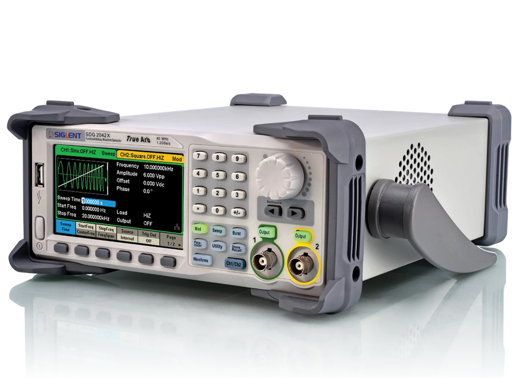
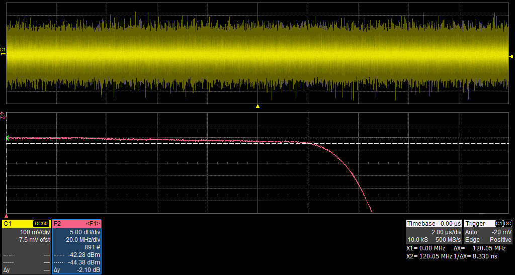
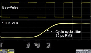
SIGLENT’s SDG800 Arbitrary Waveform Generators output waveform functions up to 5 MHz (pulse), 10 MHz (square), 30 MHz (sine) and have a sampling rate of 125 MSa/s. SDG800 signal generators are powered with SIGLENT’s EasyPulse technology which produces low jitter, fast rising/falling edges without being affected by frequency, even at low duty cycle settings, allowing the user a wide range of pulse widths and transition times. This results in a much more versatile function generator than other similar DDS designs.
Max Output Frequency
Max Sampling Rate
Vertical Resolution
Waveform Length
Channels
SDG830
30 MHz
125 MSa/s
14-bit
16 kpts
1
SDG810
10 MHz
125 MSa/s
14-bit
16 kpts
1
SDG805
5 MHz
125 MSa/s
14-bit
16 kpts
1
Key Features
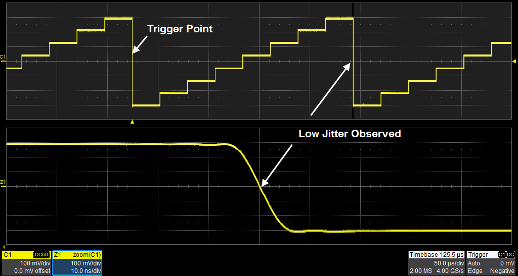
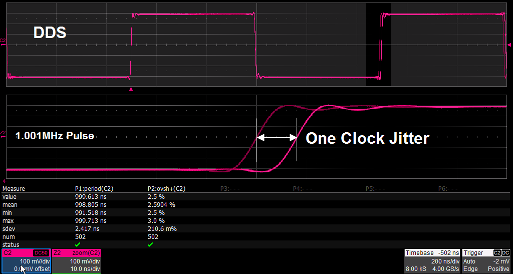
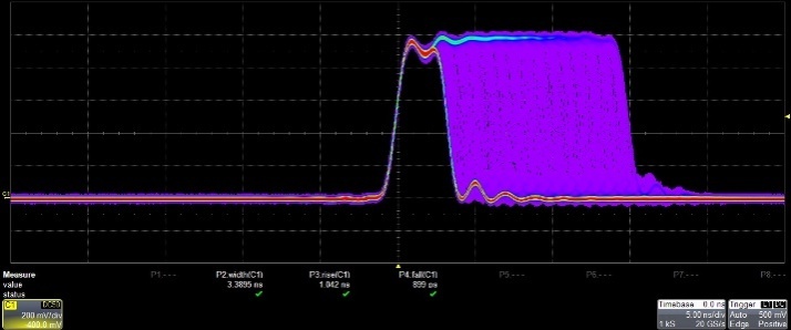
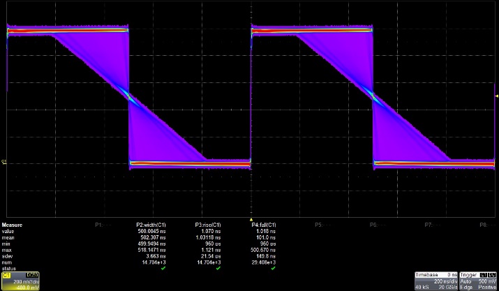
Innovative EasyPulse technology, can output pulses with low jitter and quick rising/falling edges
Standard interfaces: USB Device, USB Host, supports U-Disk storage
10 non-volatile storage spaces for user’s arbitrary waveforms
Can be seamlessly connected to SIGLENT Digital Storage Oscilloscopes
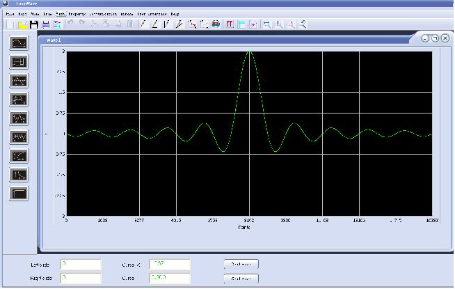
Includes EasyWave, the powerful arbitrary waveform editing software
Comparison of edge under 1KHz pulse signal
Comparison of edge adjusting range under 1KHz pulse signal
Built-in 46 kinds of arbitrary waveforms (including DC)
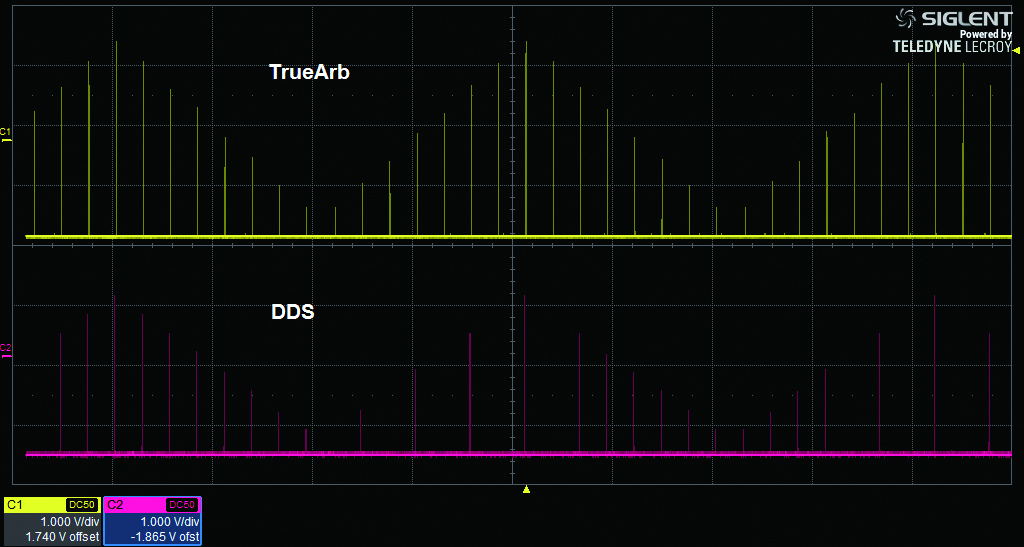
Innovative EasyPulse technology, capable of generating lower-jitter Pulse waveforms, brings a wide range and extremely high precision in pulse width and rise/fall times adjustment
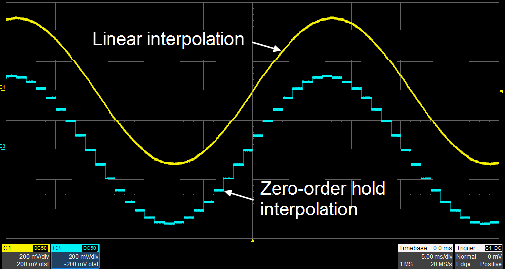
NEW: Innovative TrueArb technology supports user-defined waveforms from 2 to 16 kpts and user-defined sample rate from 1 μSa/s to 30 MSa/s
Product Overview
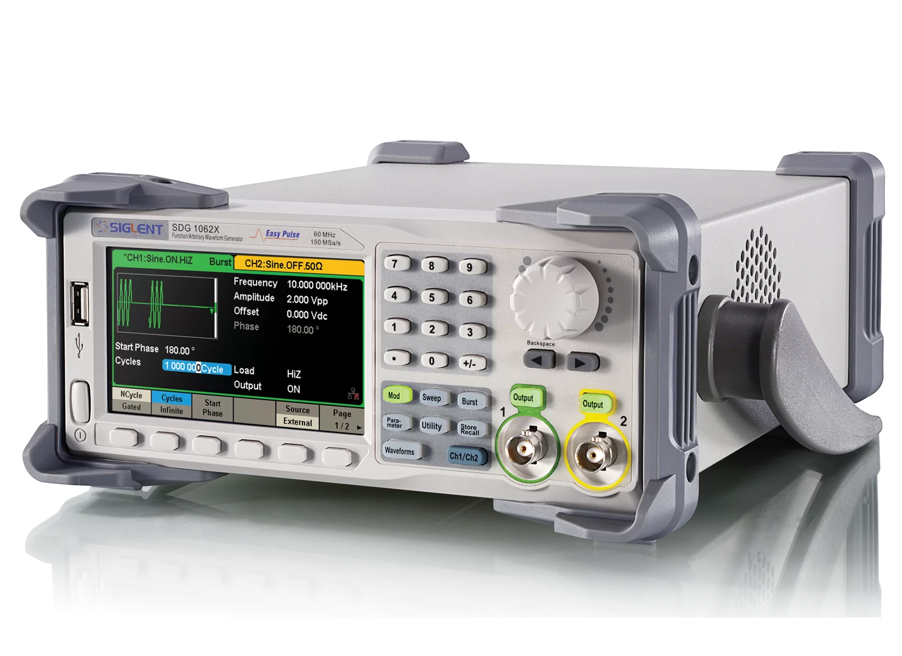
SIGLENT’s SDG1000X dual-channel arbitrary waveform generators include up to 60 MHz maximum bandwidth, 150 MSa/s sampling rate and 14-bit vertical resolution. The proprietary EasyPulse & TrueArb technique helps to solve the weaknesses inherent in traditional DDS generators when generating pulse waveforms, and the special square generator is capable of generating square waveforms up to 60 MHz in frequency with low jitter. With these advantages, SDG1000X function generators can provide users with a variety of high fidelity/low jitter signals while meeting the growing requirements of a wide range of complex and varied applications.
Max Output Frequency
Max Sampling Rate
Vertical Resolution
Waveform Length
Channels
SDG1062X
60 MHz
150 MSa/s
14-bit
16 kpts
2 CH
SDG1032X
30 MHz
150 MSa/s
14-bit
16 kpts
2 CH
Key Features
Special circuit for Square wave function, can generate Square waves up to 60 MHz with jitter less than 300 ps+0.05 ppm of period
Plenty of analog and digital modulation types: AM, DSB-AM, FM, PM, FSK, ASK, PSK and PWM
Sweep and Burst functions
Harmonics Generator function
Waveform Combining function
High precision Frequency Counter
Standard interfaces: USB Host, USB Device (USBTMC), LAN (VXI-11)
Optional interface: GPIB
4.3” TFT-LCD display
Product Characteristics
TrueArb Technology Architecture
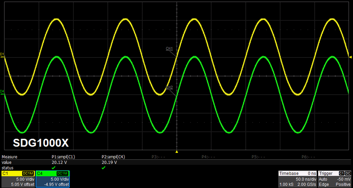
Identical dual output-channels with high performance
SDG1000X Plus Series Function/Arbitrary Waveform Generators
Dual channel, maximum output amplitude 20 Vpp
1 GSa/s Sampling rate, 16-bit vertical resolution
Arbitrary wave length 8 Mpts/CH
Multi-pulse output function
Supports PRBS up to 40 Mbps
Product Overview
SIGLENT’s SDG1000X Plus series dual-channel function/arbitrary waveform generator, with a maximum bandwidth of 60MHz, has excellent sampling system indicators of 1GSa/s sampling rate and 16-bit vertical resolution. Based on the traditional DDS technology, the innovative TrueArb and EasyPulse technologies are used to overcome the inherent defects of DDS technology in outputting arbitrary waves and square waves/pulses. It can provide users with high-fidelity, low jitter signals. In addition, SDG1000X Plus also provides PRBS pattern generation, sequence wave output, and dual pulse output functions to meet a wider range of application needs.
Max Output Frequency
Max Sampling Rate
Vertical Resolution
Waveform Length
Channels
SDG1062X Plus
60 MHz
1 GSa/s
16-bit
8 Mpts
2 CH
SDG1032X Plus
30 MHz
1 GSa/s
16-bit
8 Mpts
2 CH
SDG1022X Plus
25 MHz
1 GSa/s
16-bit
8 Mpts
2 CH
Key Features
Plenty of analog and digital modulation types: AM, DSB-AM, FM, PM, FSK, ASK, PSK and PWM
Sweep and Burst function
Harmonic function
Waveform Combining function
High precision Frequency Counter
196 built-in arbitrary waveforms
Built-in WebServer supports instrument control via web browser
Standard interfaces: USB Host, USB Device(USBTMC), LAN (VXI-11)
SDG2000X Series Function/Arbitrary Waveform Generators
Dual-channel, 120 MHz maximum bandwidth, 20 Vpp maximum output amplitude, high fidelity output with 80 dB dynamic range
High-performance sampling system with 1.2 GSa/s sampling rate and 16-bit vertical resolution. No detail in your waveforms will be lost
Innovative TrueArb technology supports user-defined waveforms from 8 to 8 Mpts and user-defined sample rate from 1 μSa/s to 75 MSa/s
Large Touch Screen Display
Easily combine waveforms through a single output, including noise and arbitrary waveforms
Product Overview
SIGLENT’s SDG2000X is a series of dual-channel function/arbitrary waveform generators with specifications of up to 120 MHz maximum bandwidth, 1.2 GSa/s sampling rate and 16-bit vertical resolution. The proprietary TrueArb & EasyPulse techniques help to solve the weaknesses inherent in traditional DDS generators when generating arbitrary, square and pulse waveforms. With advantages above, SDG2000X waveform generators can provide users with a variety of high fidelity and low jitter signals, which can meet the growing requirements of complex and extensive applications.
Max Output Frequency
Max Sampling Rate
Vertical Resolution
Waveform Length
Channels
SDG2122X
120 MHz
1.2 GSa/s
16-bit
8 pts to 8 Mpts
2
SDG2082X
80 MHz
1.2 GSa/s
16-bit
8 pts to 8 Mpts
2
SDG2042X
40 MHz
1.2 GSa/s
16-bit
8 pts to 8 Mpts
2
Key Features
Innovative EasyPulse technology, capable of generating lower jitter Square or Pulse waveforms, brings a wide range and extremely
high precision in pulse width and rise/fall times adjustment
Plenty of analog and digital modulation types: AM, DSB-AM, FM, PM, PSK, FSK, ASK and PWM
Sweep and Burst function, Harmonics mode supported
High precision Frequency Counter
Standard interfaces: USB Device, USB Host, LAN (VXI-11), and GPIB (optional)
SDG6000X Series Pulse/Arbitrary Waveform Generator
Dual-Channel, 500 MHz maximum bandwidth, 20 Vpp maximum output amplitude, high fidelity output with 80 dB dynamic range
High-performance sampling system with 2.4 GSa/s sampling rate and 16-bit vertical resolution
EasyPulse circuit lowers jitter and increases pulsed performance
Create baseband and IF IQ modulated waveforms (optional)
Product Overview
SIGLENT’s SDG6000X is a series of dual-channel Pulse/Arbitrary Waveform Generators that feature up to 500 MHz bandwidth, a maximum sample rate of 2.4 GSa/s and 16-bit vertical resolution. They also include proprietary TrueArb & EasyPulse technology that help to solve the weaknesses inherent in traditional DDS generators when generating arbitrary, square and pulse waveforms. In addition, SDG6000X waveform generators are multi-function devices which can generate Noise, IQ signals and PRBS patterns. These features enable the SDG6000X to provide a variety of high fidelity and low jitter signals, meeting the growing requirements of complex and intensive applications.
Max Output Frequency
Max Sampling Rate
Vertical Resolution
Waveform Length
Channels
SDG6022X
200 MHz
2.4 GSa/s
16-bit
20 Mpts
2
SDG6032X
350 MHz
2.4 GSa/s
16-bit
20 Mpts
2
SDG6052X
500 MHz
2.4 GSa/s
16-bit
20 Mpts
2
Key Features
Sweep and Burst function
Harmonics function
Waveform Combining function
Channel Coupling, Copy and Tracking function
196 built-in arbitrary waveforms
High precision Frequency Counter
Base Band and IF IQ signals supporting basic modulation and an arbitrary symbol rate between 250 Symb/s to 37.5 MSymb/s (optional)
Standard interfaces include: USB Host, USB Device (USBTMC), LAN (VXI-11, Socket, Telnet). GPIB Optional (Part number USB-GPIB)
Dual-channel differential/single-ended output, 16-bit LVDS/LVTTL digital bus outputs (optional)
High-performance sampling system with 5 GSa/s sample rate and 14 -bit vertical resolution
1 GHz maximum bandwidth
Generates arbitrary waveform with sample rates of 0.01 Sa/s ~ 2.5 GSa/s
Memory depth of 512 Mpts
Segmented editing /playback functions
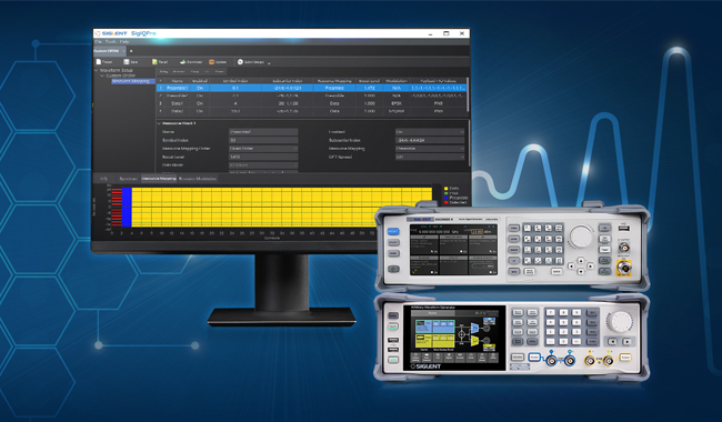
Generates vector signals with up to 500 MS/s symbol rate
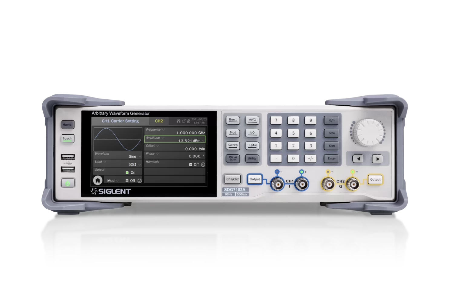
Product Overview
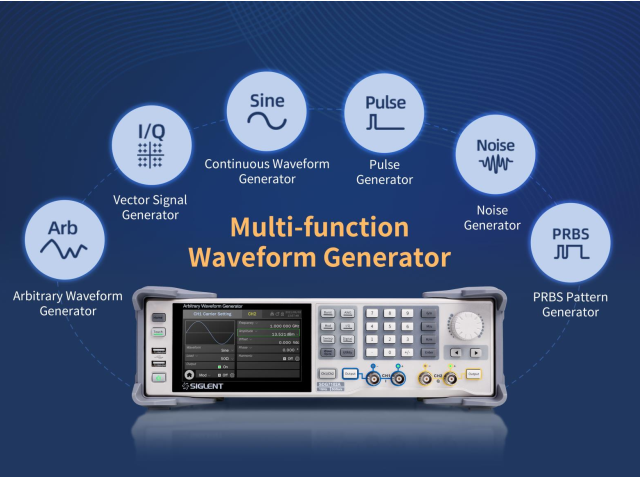
SIGLENT’s SDG7000A Arbitrary Waveform Generators feature up to 1 GHz bandwidth, a maximum sample rate of 5 GSa/s, and 14-bit vertical resolution. It can generate arbitrary waveforms point by point with a maximum 2.5 GSa/s sample rate and vector signals with a maximum of 500 MSa/s. It also has the ability to generate a variety of signals such as continuous wave, Pulse, Noise, PRBS patterns, and a 16-bit digital bus. The SDG7000A supports the generation of complex signals such as modulation, sweeping, bursting, and dual-channel copying/coupling/tracking and superposition. The outputs are user selectable for differential or single-ended connections and support a maximum output range of ± 24 V. The SDG7000A waveform generator can ensure a large amplitude under high-frequency which eliminates an external power amplifier in some applications and addresses a wider range of requirements.
Max Output Frequency
Max Sampling Rate
Vertical Resolution
Waveform Length
Channels
SDG7102A
1 GHz
5 GSa/s
14-bit
512 Mpts
2 Differential/Single-ended
SDG7052A
500 MHz
5 GSa/s
14-bit
512 Mpts
2 Differential/Single-ended
SDG7032A
350 MHz
5 GSa/s
14-bit
512 Mpts
2 Differential/Single-ended
Key Features
Generates low jitter pulses with 1 ns minimum pulse width and 500 ps minimum edge
Up to 1 GHz bandwidth and White Gaussian Noise with adjustable bandwidth
PRBS up to 312.5 Mbps
LVTTL and LVDS Digital bus options for digital signal sourcing up to 1 Gbps
Includes popular analog/digital modulation types, sweeping and bursting functions
Enhanced dual-channel operation functions: inter-channel tracking, coupling, and copying
Dual-channel superposition function
Mutual modulation between channels
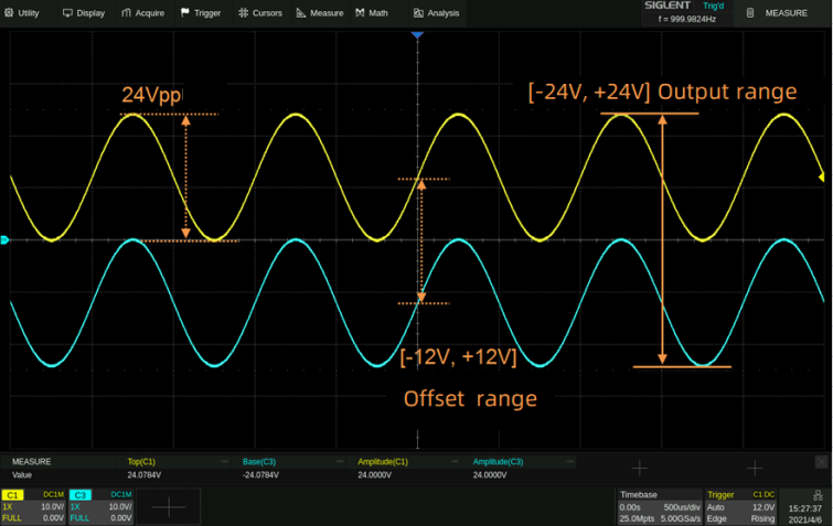
The 24 Vpp analog output is superimposed with ± 12 Vdc offset to provide a maximum output range of ± 24 V (48 V)
High precision Frequency Counter
5-inch capacitive touch screen with a resolution of 800×480
External mouse and keyboard operation
WebServer to control the instruments remotely without downloading software
Includes 10 MHz In, 10 MHz Out, Trigger In/Out, and Marker sync connections
Full SCPI command manual for easy integration into test systems
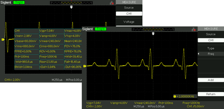
SIGLENT SDS1000DL+ Digital Storage Oscilloscopes are dual-channel, 50 MHz oscilloscopes. The SDS1000DL+ includes a 30 kpts memory depth that helps to ensure accurate waveform resolution and to capture long signal lengths. With its 7-inch TFT-LCD (800*480) screen, there is adequate screen space to help better see and analyze waveform details. Along with a 500 MSa/s sampling rate, the SDS1000DL+ oscilloscope supports 32 parameters measurements and common mathematical operations to speed up complex/repetitive measurements.
Bandwidth
Channels
Real time
sampling rate
Capture rate
Memory depth
SDS1052DL+
50 MHz
2+EXT
500 MSa/
-
32 kpts
Key Features
Supports multi-language display and embedded help
Screensaver from 1 minute to 5 hours
Digital filter and waveform recorder function
Shortcut storage function key
7-inch TFT-LCD display with 800 * 480 resolution
Multiple interfaces: USB Host, USB Device (USBTMC), LAN (VXI-11), Pass / Fail
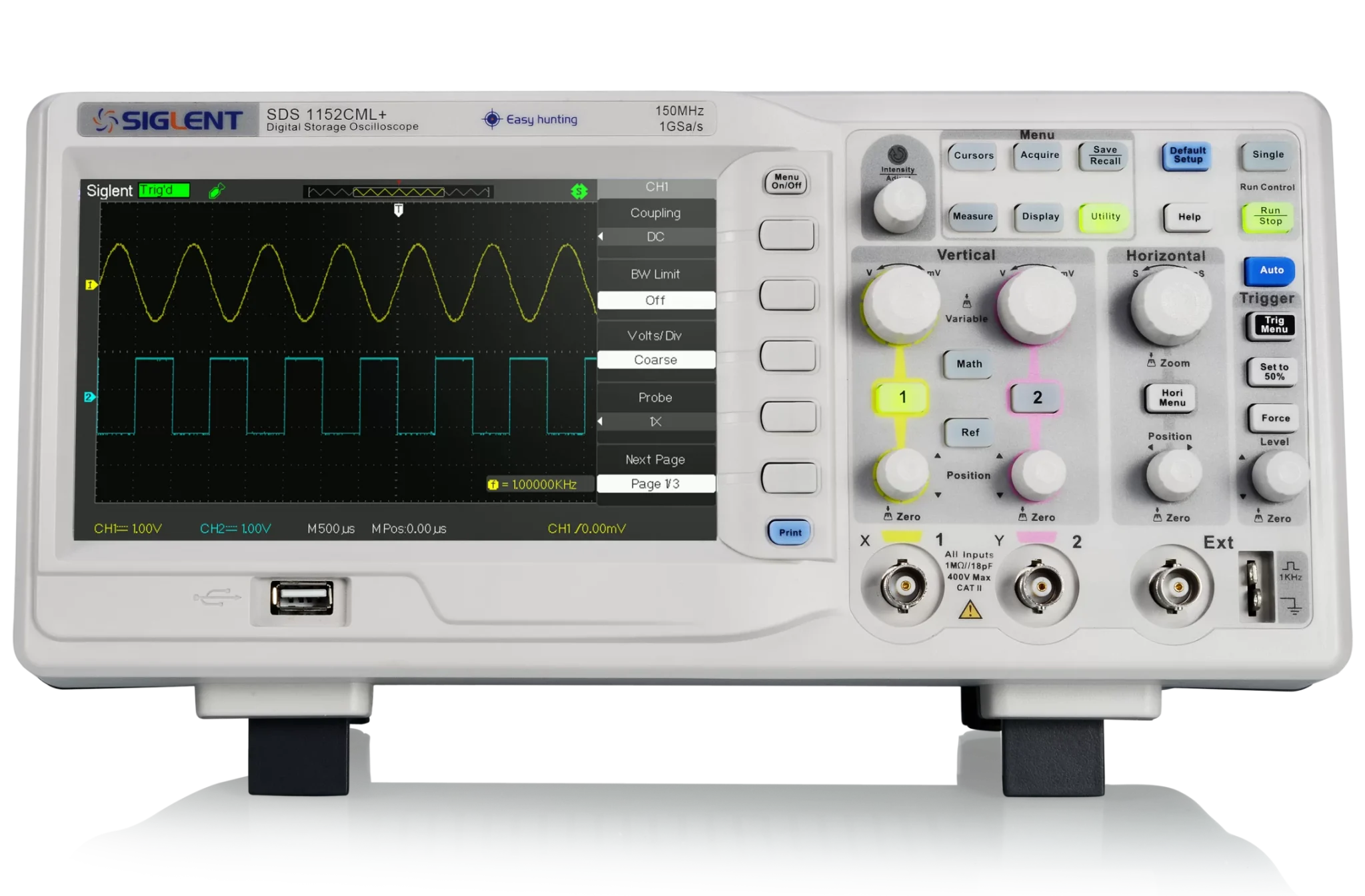
SIGLENT’s SDS1000CML+ Digital Oscilloscopes are dual-channel oscilloscopes, available in 100, and 150 MHz bandwidth models. The SDS1000CML+ includes a 2 Mpts memory depth that helps to ensure accurate waveform resolution and to capture longer signal lengths. With its 7-inch TFT-LCD (800*480) screen, there is adequate screen space to help better see and analyze waveform details. Along with a 1 GSa/s sampling rate, SDS1000CML+ digital oscilloscopes support 32 parameters measurements and common mathematical operations to speed up complex/repetitive measurements.
Bandwidth
Channels
Real time
sampling rate
Capture rate
Memory depth
SDS1152CML+
150 MHz
2+EXT
1 GSa/s
-
2 Mpts
SDS1102CML+
100 MHz
2+EXT
1 GSa/s
-
2 Mpts
Key Features
Supports multi-language display and embedded help
Screensaver from 1 minute to 5 hours
Digital filter and waveform recorder function
Shortcut storage function key
7-inch TFT-LCD display with 800 * 480 resolution
Multiple interfaces: USB Host, USB Device (USBTMC), LAN (VXI-11), Pass / Fail
Normal Memory (40 Kpts)
Long Memory (2 Mpts)
32 parameters auto measurements and 5 parameters display
Serial bus triggering and decoder supports protocols I2C, SPI, UART, CAN, LIN
Advanced measurements on full memory (14 Mpts)
Large 7-inch TFT-LCD display with 800 * 480 resolution
Starting at $399
Product Overview
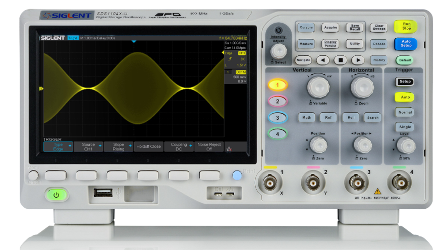
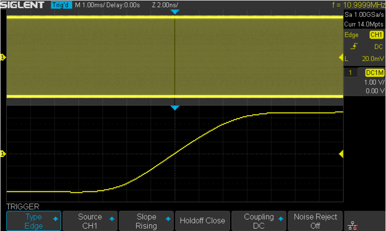
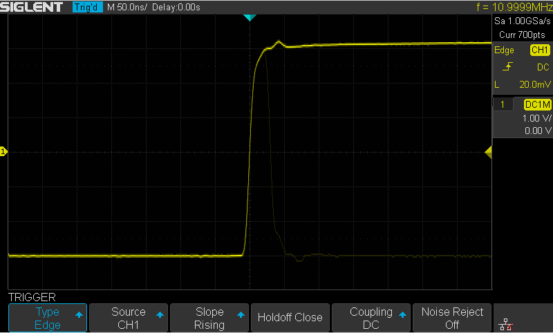
SIGLENT’s SDS1000X-U Super Phosphor Oscilloscopes are available in one bandwidth, 100 MHz. SDS1000X-U Oscilloscopes have a maximum sample rate of 1 GSa/s and a maximum record length of 14 Mpts. For ease of use, the most commonly used functions can be accessed with its user-friendly front panel design.
The SDS1000X-U series employs SPO (Super Phosphor Oscilloscope) technology that provides excellent signal fidelity and performance. It comes with an innovative digital trigger system with high sensitivity and low jitter, and a waveform capture rate of 400,000 frames/sec (sequence mode). The SDS1000X-U also employs a 256 level intensity grading display function and a color temperature display mode not found in other models in this class.
Another powerful addition is the new 128 k point FFT math function that gives this digital oscilloscope a very high-frequency resolution when observing signal spectra. Siglent’s SDS1000X-U also supports searching and navigating. The features and performance of the SDS1000X-U cannot be matched anywhere else in this price class.
Bandwidth
Channels
Real time
sampling rate
Capture rate
Memory depth
SDS1104X-U
100 MHz
4
1 GSa/s
4 00,000 wfm/s
14 Mpts
Key Features
100 MHz bandwidth
Real-time sampling rate up to 1 GSa/s
The newest generation of SPO technology
Waveform capture rates up to 100,000 wfm/s (normal mode) and 400,000 wfm/s (sequence mode)
Supports 256-level intensity grading and color temperature display modes
Record length up to 14Mpts
Digital trigger system
Intelligent trigger: Edge, Slope, Pulse Width, Window, Runt, Interval, Time out (Dropout), Pattern
Serial bus triggering and decoding (Standard), supports protocols IIC, SPI, UART, CAN, LIN
Video trigger, supports HDTV
10 types of one-button shortcuts, supports Auto Setup, Default, Cursors, Measure, Roll, History, Display/Persist, Clear Sweep, Zoom and Print
Segmented acquisition (Sequence) mode, divides the maximum record length into multiple segments (up to 80,000), according to trigger conditions set by the user
Automatic measurement function for 38 parameters as well as Measurement Statistics, Zoom, Gating, Math, History and Reference functions
History waveform record (History) function (maximum recorded waveform length is 80,000 frames)
2 or 4 analog channels, 16 logic/MSO optional on 4 channel only
Real-time sampling rate up to 1 GSa/s
Math co-processor speeds front panel operation
Waveform capture rate up to 100,000 wfm/s (normal mode), and 400,000 wfm/s (sequence mode)
Record length up to 14 Mpts, 1 Mpt FFT
On-screen Bode plot and web-browser control (standard on 4 channel only)
Product Overview
SIGLENT’s SDS1000X-E Super Phosphor Oscilloscopes are available in 100 and 200 MHz bandwidths and 2 or 4 analog channels. It has a maximum sample rate of 1 GSa/s and a standard record length of 14 Mpts. For ease-of-use, the most commonly used functions can be accessed with its user-friendly front panel design. SDS1000X-E oscilloscopes employ a new generation of SPO (Super Phosphor Oscilloscope) technology that provides excellent signal fidelity and performance. The system noise is also lower than similar products in the industry. It comes with a minimum vertical input range of 500 uV/div, an innovative digital trigger system with high sensitivity and low jitter, and a waveform capture rate of 400,000 frames/ sec (sequence mode).
SDS1000X-E digital oscilloscope also employs a 256-level intensity grading display function and a color temperature display mode not found in other models in this class. SIGLENT’s oscilloscopes support multiple powerful triggering modes including serial bus triggering. Serial decoding is free and includes IIC, SPI, UART, CAN, and LIN. History waveform recording and sequential triggering enable extended waveform recording and analysis. Another powerful addition is the new 1 Mpt FFT math function that gives the SDS1000X-E oscilloscope very high frequency resolution when observing signal spectra. The new design also includes a hardware co-processor that delivers measurements quickly and accurately. The features and performance of SIGLENT’s SDS1000X-E cannot be matched anywhere else in this price class.
Free Serial bus triggering and decoding:IIC, SPI, UART, RS232, CAN, and LIN
Video triggers and supports HDTV
Low background noise and 500 μV / div to 10 V / div voltage scales
10 types of one-button shortcuts, supports Auto Setup, Default, Cursors, Measure, Roll, History, Display/Persist, Clear Sweep, Zoom and Print
Segmented acquisition (Sequence) mode, dividing the maximum record length into multiple segments (up to 80,000), according to trigger conditions set by the user, with a very small dead time segment to capture the qualifying event.
History waveform record (History) function, the maximum recorded waveform length is 80,000 frames
Automatic measurement function on 38 parameters, supports Statistics, Gating measurement, Math measurement, History measurement and Ref measurement
1 Mpts FFT
True measurement and math can use all 14 Mpts of memory
Preset key can be customized for user settings or factory “defaults”
Security Erase mode
Highspeed hardware based Pass/ Fail function
Large 7-inch TFT-LCD display with 800 * 480 resolution
Multiple interface types: USB Host, USB Device (USB-TMC), LAN (VXI-11), Pass / Fail, Trigger Out
Waveform capture rate up to 110,000 wfm/s (normal mode), and
400,000 wfm/s (sequence mode)
Supports 256-level intensity grading and color display modes
7-inch TFT-LCD display and 10 one-button menus
Record length up to 28 Mpts
Digital trigger system
Bode plot
Product Overview
SIGLENT’s new SDS2000X-E Series Super Phosphor Oscilloscopes are available in two bandwidths; 200 MHz and 350 MHz. They each have a maximum sampling rate of 2 GSa/s and a standard record length of 28 Mpts. The most commonly used functions can be accessed with its user-friendly one-button design.
The SDS2000X-E oscilloscope series employs a new generation of SPO technology. With its excellent signal fidelity, background noise is lower than similar products in the industry. It has a minimum vertical input range of 500 uV/div, an innovative digital trigger system with high sensitivity and low jitter, and a waveform capture rate of 400,000 frames/sec (sequence mode). It also employs a 256-level intensity grading display function and a color temperature display mode not found in other models in this class. Siglent’s newest oscilloscope offering supports multiple powerful triggering modes including serial bus triggering and decoding. History waveform recording and sequential triggering allow for extended waveform records to be captured, stored, and analyzed. Also included is the deep memory FFT. This math function uses up to 1 M samples for the FFT calculation, providing the SDS2000X-E with very high frequency resolution. The hardware co-processor executes true fast measurement and math to all of 28M sample points so that there is minimal distortion on analysis. It also supports searching and navigating, on-screen Bode plot, 16 channel digital /MSO , an external USB powered 25 MHz AWG function generator module (option) and an embedded application that allows remote control via web browser. The features and high-performance of the SDS2000X-E oscilloscopes cannot be matched else anywhere at this price.
Having trouble deciding which scope is right for you?
SIGLENT’s SDS2000X Plus series Digital Storage Oscilloscopes are available in bandwidths of 350 MHz, 200 MHz and 100 MHz, have a maximum sample rate of 2 GSa/s, maximum record length of 200 Mpts/ch, and up to 4 analog channels + 16 digital channels mixed signal analysis ability.
The SDS2000X Plus series employs SIGLENT’s SPO technology with a maximum waveform capture rate of up to 120,000 wfm/s (normal mode, up to 500,000 wfm/s in Sequence mode), 256-level intensity grading display function plus a color temperature display mode. It also employs an innovative digital trigger system with high sensitivity and low jitter. The trigger system supports multiple powerful triggering modes including serial bus triggering. History waveform recording, Sequence acquisition, Search and Navigate functions allow for extended waveform records to be captured, stored, and analyzed. An impressive array of measurement and math capabilities, options for a 50 MHz waveform generator, as well as serial decoding, mask test, bode plot, and power analysis are also features of the SDS2000X Plus. A 10-bit acquisition mode helps to satisfy applications which require more than 8-bit resolution.
The large 10.1’’ capacitive touch screen supports multi-touch gestures, while the remote web control, mouse and external keyboard support greatly improve the operating efficiency of the SDS2000X Plus.
Bandwidth
Channels
Real time sampling rate
Capture rate
Memory depth
SDS2354X Plus
350 MHz
4+EXT
2 GSa/s
120,000 wfm/s
200 Mpts/ch
SDS2204X Plus
200 MHz
4+EXT
2 GSa/s
120,000 wfm/s
200 Mpts/ch
SDS2104X Plus
100 MHz
4+EXT
2 GSa/s
120,000 wfm/s
200 Mpts/ch
SDS2102X Plus
100 MHz
2+EXT
2 GSa/s
120,000 wfm/s
200 Mpts/ch
Key Features
350 MHz, 200 MHz, 100 MHz models with real-time sample rate up to 2 GSa/s. A 500 MHz bandwidth upgrade option is available for 350 MHz models.
SPO technology
Waveform capture rates up to 120,000 wfm/s (normal mode) and 500,000 wfm/s (sequence mode)
Supports 256-level intensity grading and color temperature display modes
Record length up to 200 Mpts/ch, 400 Mpts in total for all 4 channels
Digital trigger system
Intelligent trigger: Edge, Slope, Pulse, Window, Runt, Interval, Dropout, Pattern and Video (HDTV supported). Trigger zone helps to simplify advanced triggering
Serial bus triggering and decoder, supports I2C, SPI, UART, CAN, LIN (Standard) and CAN FD, FlexRay, I2S, MIL-STD-1553B, SENT, and Manchester (optional) protocols
Low background noise, features 0.5 mV/div to 10 V/div voltage scales
10-bit mode provides higher resolution and lower noise
Segmented acquisition (Sequence) mode, dividing the maximum record length into multiple segments (up to 90,000), according to trigger conditions set by the user, with a very small dead time between segments to capture the qualifying event
History waveform record (History) function for up to 90,000 triggered waveforms (frames)
Automatic measurement function on 50+ parameters, supports statistics with histogram and trend
Two Math traces, support 2 Mpts FFT, +, -, x, ÷, d/dt, ∫dt, √, average, ERES, and formula editor
Abundant data processing and analysis functions such as Search, Navigate, Mask Test, Bode plot, Power Analysis (optional) and Counter
16 digital channels
Built-in 50 MHz waveform generator (optional)
Large 10.1” TFT-LCD display with 1024×600 resolution; Capacitive touch screen supports multi-touch gestures
Multiple interfaces: USB Host, USB Device (USBTMC), LAN(VXI-11/Telnet/Socket), Pass/Fail, Trigger Out
Built-in web server supports remote control by the LAN port using a web browser; Supports SCPI remote control commands
Waveform capture rate up to 500,000 wfm/s (Sequence mode)
Sampling rate up to 2 GSa/s (interleaving mode)
Large 10.1” TFT-LCD display with 1024 * 600 resolution
Serial bus triggering and decoder, supports protocols I2C, SPI, UART, CAN, LIN, CAN FD, FlexRay, I2S, MIL-STD-1553B, SENT and Manchester
Product Overview
SIGLENT’s SDS2000X high-resolution digital oscilloscopes are based on 2 GSa/s, 12-bit Analog to Digital converters and front ends with excellent noise floor performance. SDS2000X HD oscilloscopes are available in bandwidths of 350 MHz and 200 MHz, have a maximum record length of 200 Mpts/ch, and display 4 analog channels + 16 digital channels mixed-signal analysis ability.
The SDS2000X HD series employs Siglent’s SPO technology with a maximum waveform capture rate of up to 100,000 wfm/s (normal mode, up to 500,000 wfm/s in Sequence mode), 256-level intensity grading display function plus a color temperature display mode. It also employs an innovative digital trigger system with high sensitivity and low jitter. The trigger system supports multiple powerful triggering modes including serial bus triggering. Tools such as History waveform recording, Search and Navigate functions, Mask Test, Bode Plot, Power Analysis and Histogram allow for extended waveform records to be captured, stored, and analyzed. An impressive array of measurement and math capabilities, options for a 25 MHz arbitrary waveform generator, as well as serial decoding are also features of the SDS2000X HD digital oscilloscope.
The large 10.1’’ display capacitive touch screen supports multitouch gestures, with the addition of a user-friendly UI design, which can greatly improve the operation efficiency. It also supports mouse control and remote web control over LAN.
Bandwidth
Channels
Real time sampling rate
Capture rate
Memory depth
SDS2204X HD
200 MHz
4+EXT
2 GSa/s
500,000 wfm/s (Sequence mode)
200 Mpts/ch
SDS2354X HD
350 MHz
4+EXT
2 GSa/s
500,000 wfm/s (Sequence mode)
200 Mpts/ch
Key Features
12-bit High Resolution
12-bit Analog-Digital Convertors with sample rate up to 2 GSa/s
Front ends with 70 μVrms noise floor @ 500 MHz bandwidth and 0.5% DC gain accuracy
4 analog channels, up to 350 MHz bandwidth (upgradable to 500 MHz)
SPO technology
Waveform capture rate up to 100,000 wfm/s (normal mode), and 500,000 wfm/s (sequence mode)
Supports 256-level intensity grading and color temperature display modes
Up to 200 Mpts/ch record length
Digital trigger system
Intelligent trigger: Edge, Slope, Pulse, Window, Runt, Interval, Dropout, Pattern, Qualified, Nth edge, Setup/hold, Delay and Video (HDTV supported). Zone Trigger simplifies advanced triggering
Serial bus triggering and decoder, supports protocols I2C, SPI, UART, CAN, LIN, CAN FD, FlexRay, I2S, MIL-STD-1553B, SENT and Manchester
Segmented acquisition (Sequence) mode, dividing the maximum record length into multiple segments (up to 80,000), according to trigger conditions set by the user, with a very small dead time between segments to capture the qualifying event
History waveform record (History) function, the maximum recorded waveform length is 80,000 frames
Automatic measurements on 50+ parameters, supports statistics with histogram, track, trend, Gating measurement, and measurements on Math, History and Ref
2 Math traces (2 Mpts FFT, addition, subtraction, multiplication, division, integration, differential, square root, etc.), supports formula editor
Abundant data analysis functions such as Search, Navigate, Digital Voltmeter, Counter, Waveform Histogram, Bode plot and Power Analysis
High Speed hardware-based Average, ERES; High Speed hardware-based Mask Test function, with Mask Editor tool for creating user-defined masks
16 digital channels
Built-in 25 MHz waveform generator
Large 10.1” TFT-LCD display with 1024 * 600 resolution; Capacitive touch screen supports multi-touch gestures
Interfaces include: USB Hosts, USB Device (USBTMC), LAN (VXI-11/Telnet/Socket), Pass/Fail, Trigger Out
Built-in web server supports remote control over the LAN port using a web browser. Supports SCPI remote control commands. Supports external mouse and keyboard
SIGLENT’s SDS5000X series Digital Storage Oscilloscopes are available in bandwidths of 1 GHz, 500 MHz and 350 MHz, have a maximum sample rate of 5 GSa/s, maximum record length of 250 Mpts/ch, and display up to 4 analog channels + 16 digital channels mixed signal analysis ability.
SDS5000X Digital Oscilloscopes feature Siglent’s SPO technology with a maximum waveform capture rate of up to 110,000 wfm/s (normal mode, up to 500,000 wfm/s in Sequence mode), 256-level intensity grading display function plus a color temperature display mode. Oscilloscopes also employ an innovative digital trigger system with high sensitivity and low jitter. The trigger system supports multiple powerful triggering modes including serial bus triggering. History waveform recording, Sequence acquisition, Search and Navigate functions allow for extended waveform records to be captured, stored, and analyzed. An impressive array of measurement and math capabilities, options for a 25 MHz arbitrary waveform generator, as well as serial decoding are also features of the SDS5000X Super Phosphor Oscilloscopes.
The large 10.1’’ display capacitive touch screen supports multi-touch gestures, with the addition of user-friendly one-button design for most commonly used functions, can greatly improve the operation effciency of the SDS5000X. It also supports mouse and external keyboard control.
1 GHz, 500 MHz, 350 MHz models with real-time sample rate up to 5 GSa/s
SPO technology
Waveform capture rates up to 110,000 wfm/s (normal mode), and 500,000 wfm/s (sequence mode)
Supports 256-level intensity grading and color temperature display modes
Record length up to 250 Mpts
Digital trigger system
Intelligent trigger: Edge, Slope, Pulse, Window, Runt, Interval, Dropout, Pattern, Qualified and Video (HDTV supported). Trigger zones helps to simplify advanced triggering
Serial bus triggering and decoder supports I2C, SPI, UART, CAN, LIN (Standard) and CAN FD, FlexRay, I2S, MIL-STD-1553B, SENT, and Manchester (optional) protocols
Low background noise, supports 0.5 mV/div to 10 V/div voltage scales
Segmented acquisition (Sequence) mode, dividing the maximum record length into multiple segments (up to 100,000), according to trigger conditions set by the user, with a very small dead time between segments to capture the qualifying event
History waveform record (History) function, the maximum recorded waveform length is 100,000 frames
Automatic measurement function on 50+ parameters, supports statistics with histogram,trend, Gating measurement, Math measurement, History measurement and Ref measurement
Math function (2 Mpts FFT, addition, subtraction, multiplication, division, integration, differential, square root), supports formula editor
Abundant data analysis functions such as Search, Navigate, Digital Voltmeter, Counter, Waveform Histogram, Bode plot and Power Analysis
SAP2500, SAP2500D, 2.5 GHz active single ended and differential probes
Product Overview
SIGLENT’s SDS6000A series Digital Storage Oscilloscopes are available in bandwidths of 2 GHz, 1 GHz, and 500 MHz, have a sample rate of 5 GSa/s (10 GSa/s ESR) at each channel, a maximum record length of 500 Mpts, and display up to 4 analog channels + 16 digital channels mixed-signal analysis ability.
The SDS6000A series employs Siglent’s SPO technology with a maximum waveform capture rate of up to 170,000 wfm/ s (normal mode, up to 750,000 wfm/s in Sequence mode), 256-level intensity grading display function plus a color temperature display mode. It also employs an innovative digital trigger system with high sensitivity and low jitter. The trigger system supports multiple powerful triggering modes including serial bus triggering. Tools such as History waveform recording, Search and Navigate functions, Mask Test, Bode Plot, Power Analysis, and Eye/Jitter Analysis allow for extended waveform records to be captured, stored, and analyzed. An impressive array of measurement and math capabilities, options for a 25 MHz arbitrary waveform generator, as well as serial decoding are also features of the SDS6000A Digital Oscilloscope.
The large 12.1” display capacitive touch screen supports multi-touch gestures, with the addition of user-friendly UI design, which can greatly improve the operation efficiency. It also supports mouse control and remote web control over LAN.
Bandwidth
Channels
Real time sampling rate
Capture rate
Memory depth
SDS6054A
500 MHz
4 + EXT
5 GSa/s (10 GSa/s ESR) per channel
Normal mode: 170,000 wfm/s; Sequence mode: 750,000 wfm/s
500 Mpts
SDS6104A
1 GHz
4 + EXT
5 GSa/s (10 GSa/s ESR) per channel
Normal mode: 170,000 wfm/s; Sequence mode: 750,000 wfm/s
500 Mpts
SDS6204A
2 GHz
4 + EXT
5 GSa/s (10 GSa/s ESR) per channel
Normal mode: 170,000 wfm/s; Sequence mode: 750,000 wfm/s
500 Mpts
Key Features
4 analog channels, up to 2 GHz bandwidth with 5 GSa/s (10 GSa/s ESR) sample rate at each channel
Waveform capture rates up to 170,000 wfm/s (normal mode), and 750,000 wfm/s (sequence mode)
Supports 256-level intensity grading and color temperature display modes
500 Mpts Record length in total for all 4 channels
Digital trigger system
Intelligent trigger: Edge, Slope, Pulse, Window, Runt, Interval, Dropout, Pattern, Qualified, Nth edge, Setup/Hold, Delay, and Video (HDTV supported). Zone Trigger simplifies advanced triggering
Serial bus triggering and decoder, supports protocols I2C, SPI, UART, CAN, LIN, CAN FD, FlexRay, I2S, MIL-STD-1553B, SENT, and Manchester
Segmented acquisition (Sequence) mode, dividing the maximum record length into multiple segments (up to 80,000), according to trigger conditions set by the user, with a very small dead time between segments to capture the qualifying event
History waveform record (History) function, the maximum recorded waveform length is 80,000 frames
Automatic measurements on 50+ parameters supports statistics with histogram, track, trend, Gating measurement, and measurements on Math, History, and Ref
4 Math traces (8 Mpts FFT, addition, subtraction, multiplication, division, integration, differential, square root, etc.), supports formula editor
Abundant data analysis functions such as Search, Navigate, Digital Voltmeter, Counter, Waveform Histogram, Bode plot, Power Analysis and Eye/Jitter Analysis
High-Speed hardware-based Average, Hi-Res; High Speed hardware-based Mask Test function, with Mask Editor tool for creating user-defined masks
Large 12.1” TFT-LCD display with 1280 * 800 resolution; Capacitive touch screen supports multi-touch gestures
Interfaces include: USB Hosts, USB Device (USBTMC), LAN(VXI-11/Telnet/Socket), micro SD card, Pass/Fail, Trigger Out, HDMI
Built-in web server supports remote control over the LAN port using a web browser. Supports SCPI remote control commands. Supports external mouse and keyboard
SIGLENT’s SDS3000X HD series Digital Storage Oscilloscopes are available in bandwidths of 1 GHz, 500 MHz and 350 MHz, have 12-bit ADCs with sample rate up to 4GSa/s, maximum record length of 400 Mpts/ch, and display up to 4 analog channels + 16 digital channels for high performance mixed signal analysis.
The SDS3000X HD series employs Siglent’s SPO technology with a maximum waveform capture rate of up to 200,000 wfm/ s, 256-level intensity grading display function plus a color temperature display mode. It also employs an innovative digital trigger system with high sensitivity and low jitter. The trigger system supports multiple powerful triggering modes including serial bus triggering. Tools such as History waveform recording, Search and Navigate functions, Mask Test, Bode Plot and Power Analysis allow for extended waveform records to be captured, stored, and analyzed. An impressive array of measurement and math capabilities, options for a 50 MHz arbitrary waveform generator, as well as serial decoding are also features of the SDS3000X HD .
The large 10.1’’ display capacitive touch screen supports multi-touch gestures, with the addition of user-friendly UI design, can greatly improve the operational efficiency. It also supports mouse control, and remote web control over LAN.
Features:
350 MHz, 500 MHz, 1GHz models
12-bit high resolution
Sampling rate up to 4 GSa/s
Memory depth up to 400 Mpts
Waveform capture rate up to 890,000 wfm/s (Sequence mode)
Noise floor as low as 125 μVrms at 1 GHz full bandwidth
Key Features
4 analog channels, up to 1 GHz bandwidth with up to 4GSa/s sample rate
12-bit ADC
Low background noise: 125 μVrms @ 1 GHz bandwidth
SPO technology
Waveform capture rates up to 200,000 wfm/s in Normal mode and 890,000 wfm/s in Sequence mode
Supports 256-level intensity grading and color temperature display modes
Up to 400 Mpts/ch record length
Digital trigger system
Intelligent trigger: Edge, Slope, Pulse, Window, Runt, Interval, Dropout, Pattern, Qualified, Nth edge, Setup/hold, Delay and Video (HDTV supported). Zone Trigger simplifies advanced triggering
Serial bus triggering and decoder, supports protocols I2C, SPI, UART, CAN, LIN, CAN FD, FlexRay, I2S, MIL-STD-1553B, SENT, Manchester and ARINC429
Segmented acquisition (Sequence) mode, dividing the maximum record length into multiple segments (up to 80,000), according to trigger conditions set by the user, with a very small dead time between segments to capture the qualifying event
History waveform record (History) function, the maximum recorded waveform length is 80,000 frames
Automatic measurements on 50+ parameters, supports statistics with histogram, track, trend, Gating measurement, and measurements on Math, History and Memory traces
4 Math traces (4 Mpts FFT, Filter, addition, subtraction, multiplication, division, integration, differential, square root, etc.), supports formula editor
Abundant data analysis functions such as Search, Navigate, Digital Voltmeter, Counter, Waveform Histogram, Bode plot and Power Analysis
High Speed hardware-based Average, ERES; High Speed hardware-based Mask Test function, with Mask Editor tool for creating user-defined masks
16 digital channels
External 50 MHz waveform generator (optional)
Large 10.1” TFT-LCD display with 1024 * 600 resolution; Capacitive touch screen supports multi-touch gestures
Interfaces include: 2x USB 3.0 Host,1x USB 2.0 Host , USB 3.0 Device (USBTMC),1000M LAN ((VXI-11/Telnet/Socket/LXI)), External Triger In, Aux Out (Pass/Fail, Trigger Out)
Built-in web server supports remote control over the LAN port using a web browser. Supports SCPI remote control commands. Supports external mouse and keyboard.
Professional Windows® Software to Communicate with CAN and CAN FD Buses
The PCAN-Explorer 6 is a versatile, professional program for working with CAN and CAN FD networks. The user is not just limited to the observation of the CAN traffic. Manual or periodic transmission of messages or entire transmission lists allows him a direct influence, for example, for control purposes or simulations.
The PCAN-Explorer 6 can connect to several CAN and CAN FD buses at the same time. Unlike previous versions, the hardware type of used PEAK CAN interfaces is no longer a limiting factor.
A central point in the use of the program is the symbolic representation of the CAN messages and their payload. With the help of Symbol files, the hexadecimal information is transformed into a readable and vivid format.
Since version 6, the trace function, in addition to recording the data traffic, allows also the playback of existing traces. The recordings and incoming CAN messages can be filtered using various criteria.
Special requirements as well as the automation of complex processes can be implemented with macros, VBScript, and callback functions. The sophisticated implementation of VBScript accesses the extensive object model of the PCAN-Explorer 6.
Furthermore, the functionality of the PCAN-Explorer can be extended by add-ins. PEAK-System offers add-ins that provide even better opportunities to analyze and influence data. The Plotter produces a graphical representation of the signals‘ time course by live recording or on the basis of traces. The Instruments Panel is used for an own arrangement of various displays, controls, and switches. Further add-ins enable the import of third-party configurations based on the CANdb format and add the support for the J1939 protocol.
EAN
Description
IPEH-002064
PCAN-Explorer 6: Plotter Add-in 6
-Optional Function Upgrade for the PCAN-Explorer
IPES-006088
PCAN-Explorer 6: Instruments Panel Add-in 6
-Optional Function Upgrade for the PCAN-Explorer
IPES-006086
PCAN-Explorer 6: CANdb Import Add-in 6
-Optional Function Upgrade for the PCAN-Explorer
IPES-006089
PCAN-Explorer 6: J1939 Add-in 6
-Optional Function Upgrade for the PCAN-Explorer
T-Adapters for a Tap Connection on to a CAN or CAN FD Bus
The PCAN-T-Adapter and PCAN-Mini-T-Adapter create a tap connection to the data cables and the ground within a CAN bus in order to be able to connect a further CAN node. In this case, the CAN node is not terminated.
The adapter with a D-Sub socket connector and a three-pin screw terminal block allows easy connection of open cable ends of a CAN bus to a D-Sub connector. This allows customers to produce all conceivable connection variants themselves in a short time. Not only our PCAN products can thus be connected more flexibly to CAN buses.
The D-Sub socket is assigned according to CiA® 106. A CAN bus termination can be added by the customer using an SMD or wired resistor on prepared solder pads.
The PCAN-USB X6 is a CAN FD interface for the USB port which allows the connection of up to 6 CAN FD or CAN busses. The device is therefore best suited for working with multiple CAN networks like the use in test benches with hardware-in-the-loop (HIL) simulations for motor vehicles or in the product line testing of CAN-based products.
The PCAN-USB X6 is installed in an aluminum profile casing and is shipped in versions with D-Sub connectors or M12 circular connectors. Especially the M12 version is suitable for use in harsh environments. In addition, a galvanic isolation of up to 300 Volts between the PC and the CAN side is guaranteed for the decoupled versions.
The CAN FD standard (CAN with Flexible Data rate) is primarily characterized by higher bandwidth for data transfer. The maximum of 64 data bytes per CAN FD frame (instead of 8 so far) can be transmitted with bit rates up to 12 Mbit/s. CAN FD is downward-compatible to the CAN 2.0 A/B standard, thus CAN FD nodes can be used in existing CAN networks. However, in this case the CAN FD extensions are not applicable.
The monitor software PCAN-View and the programming interface PCAN-Basic for the development of applications with CAN connection are included in the scope of supply and support the standard CAN FD.
ISO / Non-ISO CAN FD
Since the first implementations of CAN FD, the protocol has been improved and is now included in the standard ISO 11898-1. The revised CAN FD standard is not compatible with the original protocol.
PEAK-System takes this into account by supporting both protocol versions with their CAN FD interfaces. If required, the user can switch to the CAN FD protocol used in the environment by software („Non-ISO“ and „ISO“). Devices delivered until February 2015 need a firmware update for this functionality. If you are interested and for further information, please contact info@peak-system.com.
Options:
EAN
Description
IPEH-004062
PCAN-USB X6 with D-Sub connectors
IPEH-004063
PCAN-USB X6 with M12 circular connectors galv. isolated
The CAN FD adapter PCAN-USB FD allows the connection of CAN FD and CAN networks to a computer via USB. A galvanic isolation of up to 500 Volts decouples the PC from the CAN bus. The simple handling and its compact plastic casing make the adapter suitable for mobile applications.
The CAN FD standard (CAN with Flexible Data rate) is primarily characterized by higher bandwidth for data transfer. The maximum of 64 data bytes per CAN FD frame (instead of 8 so far) can be transmitted with bit rates up to 12 Mbit/s. CAN FD is downward-compatible to the CAN 2.0 A/B standard, thus CAN FD nodes can be used in existing CAN networks. However, in this case the CAN FD extensions are not applicable.
The monitor software PCAN-View and the programming interface PCAN-Basic for the development of applications with CAN connection are included in the scope of supply and support the standard CAN FD.
ISO / Non-ISO CAN FD
Since the first implementations of CAN FD, the protocol has been improved and is now included in the standard ISO 11898-1. The revised CAN FD standard is not compatible with the original protocol.
PEAK-System takes this into account by supporting both protocol versions with their CAN FD interfaces. If required, the user can switch to the CAN FD protocol used in the environment by software („Non-ISO“ and „ISO“). Devices delivered until February 2015 need a firmware update for this functionality. If you are interested and for further information, please contact info@peak-system.com.
Plug & play 2xCAN/LIN WiFi logger records timestamped CAN data (Classical/CAN FD) to the extractable 8 GB industrial SD card. More
CAN bus data loggers – simple-to-use. pro specs. interoperable.
Your data, your way. Easily log CAN data from your vehicle / machine – and extract it via SD or WiFi.
Process the interoperable data in your favorite tools – or via 100% free open source software/APIs.
The Testing Laboratory for Safety Components of TÜV SÜD Rail GmbH has certified that Testwell CTC++
is suitable to be used in safety-related development according to IEC 61508:2010 for any SIL,
is qualified to be used in a standard-compliant development process according to ISO 26262:2018 for any ASIL,
is suitable to be used in safety-related software development according to EN 50128:2011/A2:2020 for any SIL,
is suitable to be used in safety related development according to IEC 62304:2006+A1:2015 for any software safety class.
Background:
TÜV certification refers to a quality and safety certification provided by Technischer Überwachungsverein (TÜV), a German organization. TÜV tests and certifies products, services, and management systems to ensure they meet specific safety and quality standards.
Why You Would Want TÜV Certification:
Safety Assurance: TÜV certification indicates that a product has undergone rigorous testing to ensure safety and compliance with relevant regulations.
Quality Control: It helps businesses demonstrate their commitment to high-quality standards, which can enhance customer trust and satisfaction.
Market Access: Some markets or industries require TÜV certification as a prerequisite for selling certain products. Having it can open up more opportunities.
Competitive Advantage: Products with TÜV certification may stand out in the marketplace, helping businesses differentiate themselves from competitors.
Regulatory Compliance: TÜV certification can help ensure that products comply with national and international regulations, reducing the risk of legal issues.
Consumer Confidence: Consumers often prefer products that are certified, as it gives them reassurance about the product’s reliability and safety.
Overall, TÜV certification can enhance credibility, support compliance, and ultimately lead to increased sales and customer loyalty.
These cables are needed to set up a CAN bus and are specially designed to be used in a CAN environment. If two High-speed CAN hubs need a simple direct connection between them, the PCAN-Cable 2 with integrated termination can be used. The PCAN-Cable 1 is suitable for putting together a CAN bus which shall contain tap connections and separate termination (PCAN-T-Adapter and PCAN-Term products).
The PCAN-Router FD allows the connection to two CAN FD or CAN buses. Based on a ARM Cortex M4F microcontroller, the module‘s behavior and the data routing between both CAN FD channels is freely programmable. In particular, the module allows the conversion from CAN to CAN FD or vice versa. This makes it easy to accomplish the integration of CAN FD applications into existing CAN 2.0 networks.
Using the programming library and the GNU compiler for C and C++, a firmware is created and then transferred to the module via CAN. On delivery, the PCAN-Router FD is provided with a standard firmware. The corresponding source code is included as example in the scope of supply.
The module is installed in an aluminum profile casing, and is shipped in versions with two D-Sub connectors or a screw-terminal strip.
The PCAN-Router is a dual-channel CAN module whose NXP LPC21 series programmable microcontroller provides the option of using the CAN messages on both channels on a flexible basis. This gives a whole range of options for manipulation, evaluation, filtering, and routing of CAN messages.
Using the programming library and the GNU compiler for C and C++, a firmware is created and then transferred to the module via CAN. At delivery, the PCAN-Router is equipped with a standard firmware that forwards CAN messages 1:1 between both channels at 500 kbit/s. The corresponding source code is included as example in the scope of supply.
The module is installed in an aluminum profile casing, and is shipped in versions with two D-Sub connectors or a screw-terminal strip.
PCAN-RS-232 is a programmable module for the communication between RS-232 and CAN. The conversion of data traffic is done via a NXP LPC21 series microcontroller.
The behavior of the PCAN-RS-232 can be programmed freely for specific applications. The firmware is created using the included development package with GNU compiler for C and C++ and is then transferred to the module via CAN. Various programming examples facilitate the implementation of own solutions.
On delivery the PCAN-RS-232 is provided with a standard firmware that routes from CAN to RS-232 and vice versa. It allows to configure the data transfer as well as the hardware with serial control commands. The corresponding source code is included as an example in the scope of supply.