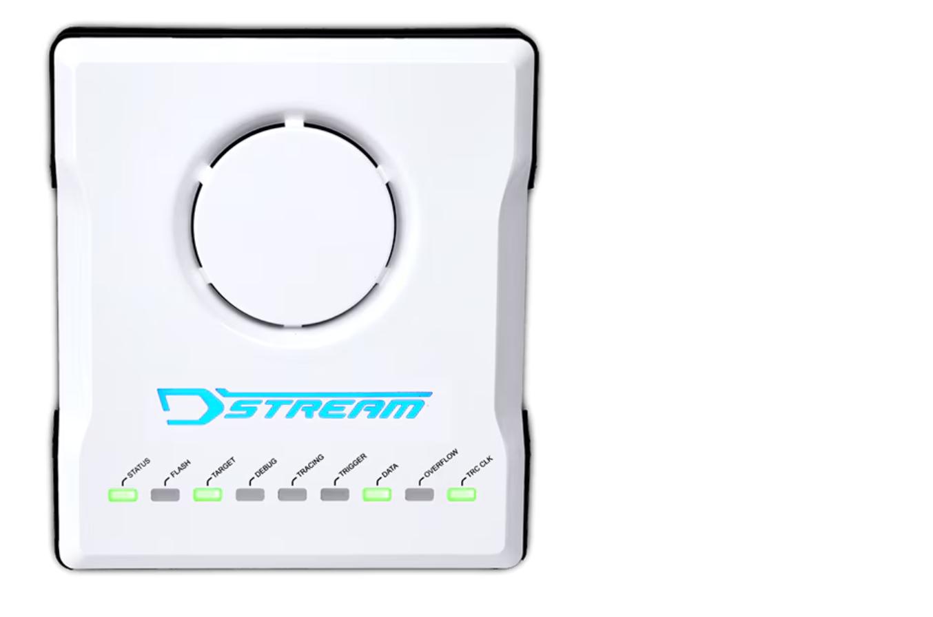
DSTREAM-ST is Arm’s high-performance debug and parallel streaming trace probe, built for work that goes beyond a single Cortex-M part: multi-core and multi-processor SoC bring-up, low-level driver and RTOS bring-up, and CoreSight-based debug and trace across any Arm architecture from Armv4 onward. It’s driven by Arm Development Studio.
Highlights
- 4-bit wide trace capture at up to 300 MHz DDR (600 Mbit/s per pin), for total trace bandwidth up to 2.4 Gbps
- JTAG clock of up to 180 MHz for fast software development, plus adaptive JTAG clock rates
- USB 3.0 and Gigabit Ethernet connectivity, for direct or remote/rack-mounted host connections
- Support for up to 4096 CoreSight devices (including CPUs), remote target reset, and device bring-up/test utilities
- Flexible architecture supporting 3rd-party IP and debuggers, not locked to one vendor’s silicon
Where it earns its keep
- New SoC and multi-core bring-up, where fast, adaptive JTAG and deep CoreSight device support matter more than a single-core Cortex-M debug session
- Low-level driver and RTOS bring-up on new hardware
- Streaming instruction/data trace for performance analysis across complex, multi-processor designs
Key Specifications
| Spec | Value |
|---|
| Debug protocol | JTAG and Serial-Wire Debug |
| Trace capture | 4-bit wide, up to 300 MHz DDR (600 Mbit/s per pin) |
| Bandwidth | Total trace bandwidth up to 2.4 Gbps |
| JTAG clock | Up to 180 MHz |
| Connectivity | USB 3.0 / Gigabit Ethernet |
| Interface Vref | 1.2V – 3.3V (configurable by target) |
| Minimum software | Arm Development Studio 2018.0 or DS-5 5.27 |
The Arm Keil ULINK family is Arm’s own line of USB debug and trace probes for Cortex-M microcontrollers — the hardware that sits between a PC and a target board, providing the JTAG/SWD connection Arm Keil MDK or Arm Development Studio needs to debug and program the chip. Three models — ULINK2, ULINKplus, and ULINKpro — cover everything from everyday run/stop debugging to full instruction trace and on-probe power measurement, so the probe can be matched to what a project actually needs.
Highlights
- ULINK2 covers core run/stop debug, breakpoints, memory/register access, and Flash programming — the entry point for day-to-day Cortex-M work
- ULINKpro adds full instruction trace up to 800 Mbit/s, code coverage, execution profiling, and performance analysis for Cortex-M3/M4/M7/M33
- ULINKplus adds 1kV isolated power measurement and nine configurable I/O pins for correlating energy use with source-level execution and driving test automation
- All three connect over USB 2.0 with no external power supply required
Where it earns its keep
- Day-to-day Cortex-M application debug and Flash programming on ULINK2, scaling up to ULINKpro when intermittent faults or performance bottlenecks need full instruction trace
- Power-aware firmware development on ULINKplus, correlating current draw directly against the line of code that caused it
- Automated test and CI setups using ULINKplus’s configurable I/O pins
Key Specifications
| Model | Trace | Debug clock | Power measurement |
|---|
| ULINK2 | Data trace to 1 Mbit/s | JTAG/SWD to 10 MHz | — |
| ULINKplus | Data trace to 50 Mbit/s | JTAG/SWD to 10 MHz | Yes (1kV isolated) |
| ULINKpro | Instruction trace to 800 Mbit/s | JTAG/SWD to 50 MHz | — |
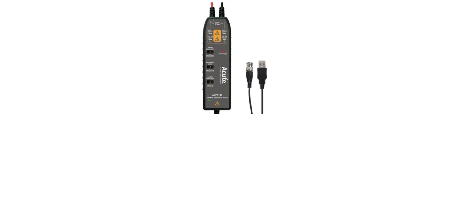
The USB-powered counterpart to the ADP5100-B — 3500V/100MHz isolated measurement, for continuous unattended operation.
Highlights
- 3500V input voltage, 100MHz bandwidth
- 50x/500x attenuation, 10Mohm/1pF input impedance
- USB powered
Key Specifications
| Spec | Value |
|---|
| Input voltage | 3500 V |
| Bandwidth | 100 MHz |
| Attenuation | 50x / 500x |
| Input impedance | 10 Mohm, 1 pF |
| Power | USB |
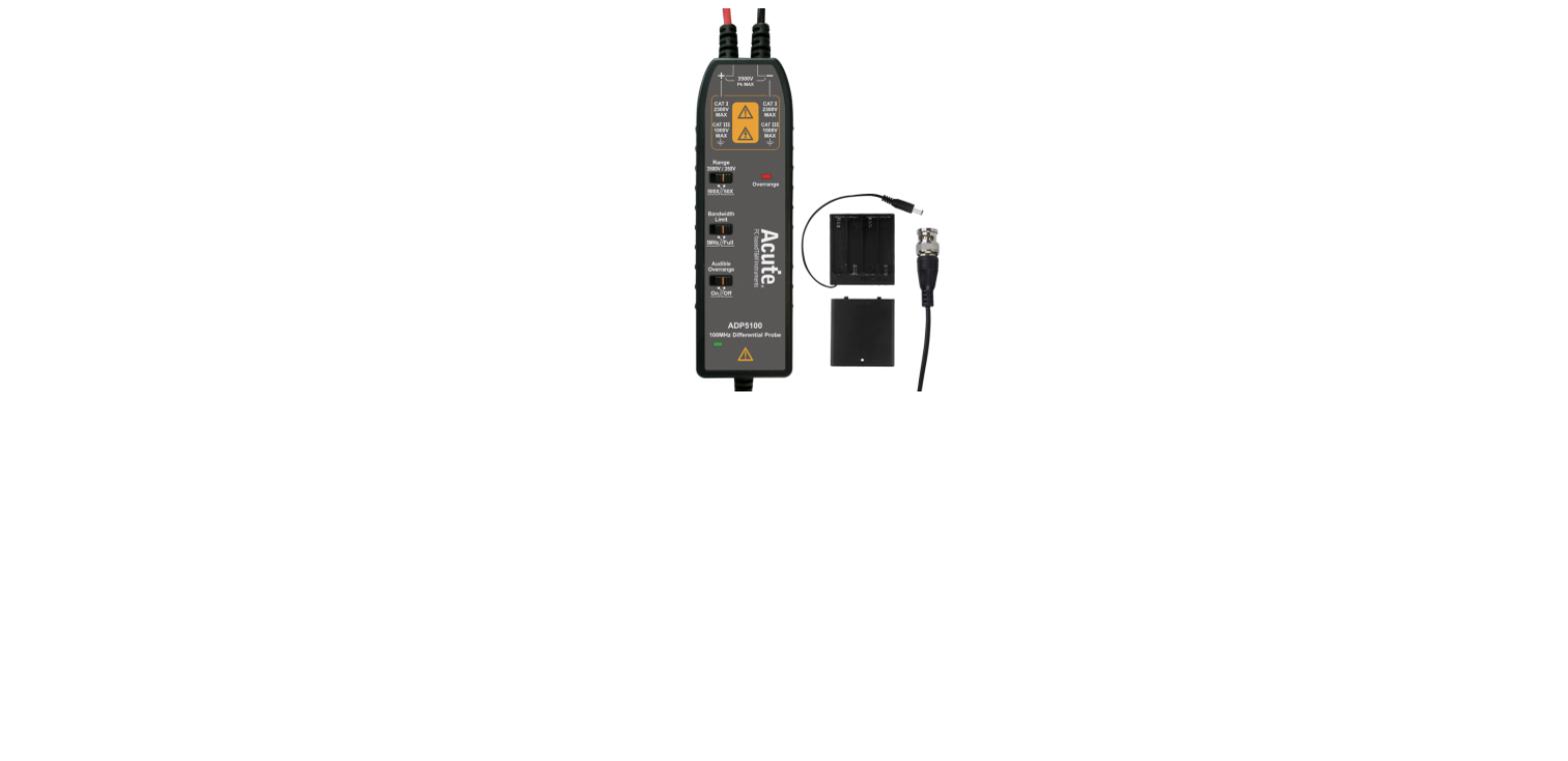
The ADP5100-B pairs the 3500V rating with 100MHz bandwidth — the fastest, highest-voltage probe in the ADP line.
Highlights
- 3500V input voltage, 100MHz bandwidth
- 50x/500x attenuation, 10Mohm/1pF input impedance
- Battery powered (AA/R6/LR6)
Key Specifications
| Spec | Value |
|---|
| Input voltage | 3500 V |
| Bandwidth | 100 MHz |
| Attenuation | 50x / 500x |
| Input impedance | 10 Mohm, 1 pF |
| Power | Battery (AA/R6/LR6) |
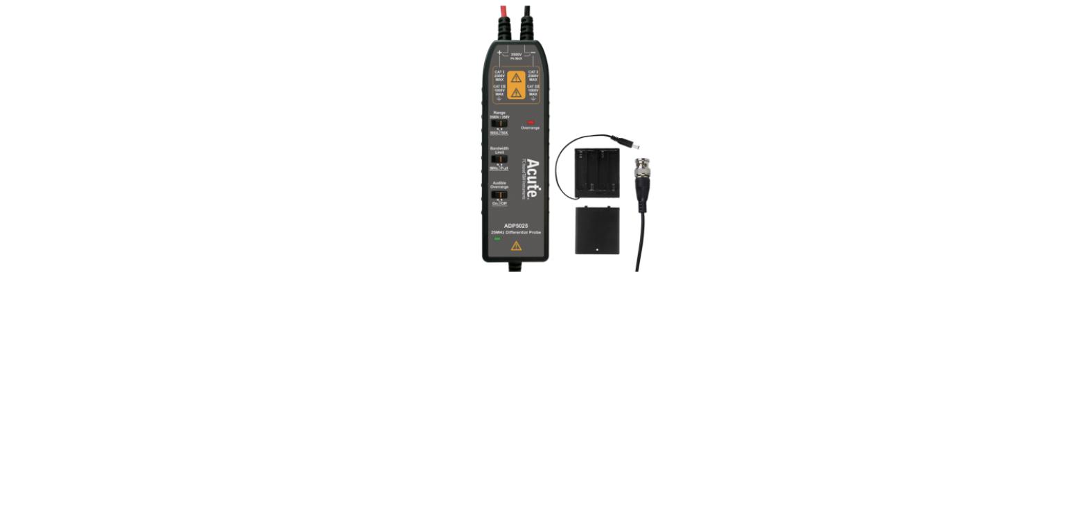
The ADP5025-B is rated to 3500V at 25MHz bandwidth — the top of Acute’s isolation range, for the highest-voltage rails in the line.
Highlights
- 3500V input voltage, 25MHz bandwidth
- 50x/500x attenuation, 10Mohm/1pF input impedance
- Battery powered (AA/R6/LR6)
Key Specifications
| Spec | Value |
|---|
| Input voltage | 3500 V |
| Bandwidth | 25 MHz |
| Attenuation | 50x / 500x |
| Input impedance | 10 Mohm, 1 pF |
| Power | Battery (AA/R6/LR6) |
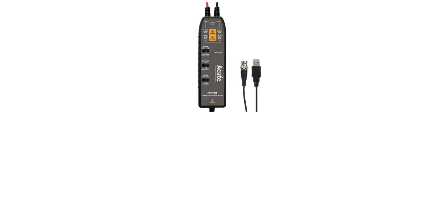
The USB-powered counterpart to the ADP5025-B — 3500V/25MHz isolated measurement, for continuous unattended operation.
Highlights
- 3500V input voltage, 25MHz bandwidth
- 50x/500x attenuation, 10Mohm/1pF input impedance
- USB powered
Key Specifications
| Spec | Value |
|---|
| Input voltage | 3500 V |
| Bandwidth | 25 MHz |
| Attenuation | 50x / 500x |
| Input impedance | 10 Mohm, 1 pF |
| Power | USB |
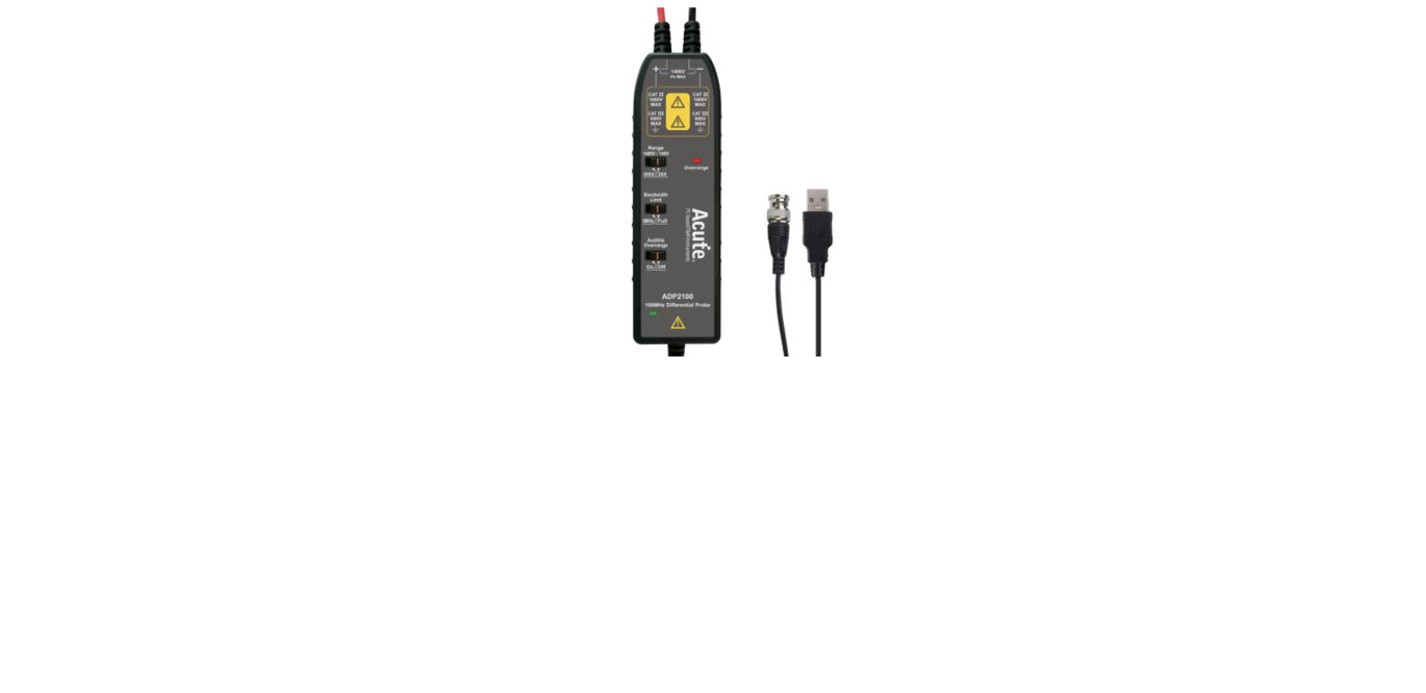
The USB-powered counterpart to the ADP2100-B — 1400V/100MHz isolated measurement, for continuous unattended operation.
Highlights
- 1400V input voltage, 100MHz bandwidth
- 20x/200x attenuation, 10Mohm/1pF input impedance
- USB powered
Key Specifications
| Spec | Value |
|---|
| Input voltage | 1400 V |
| Bandwidth | 100 MHz |
| Attenuation | 20x / 200x |
| Input impedance | 10 Mohm, 1 pF |
| Power | USB |
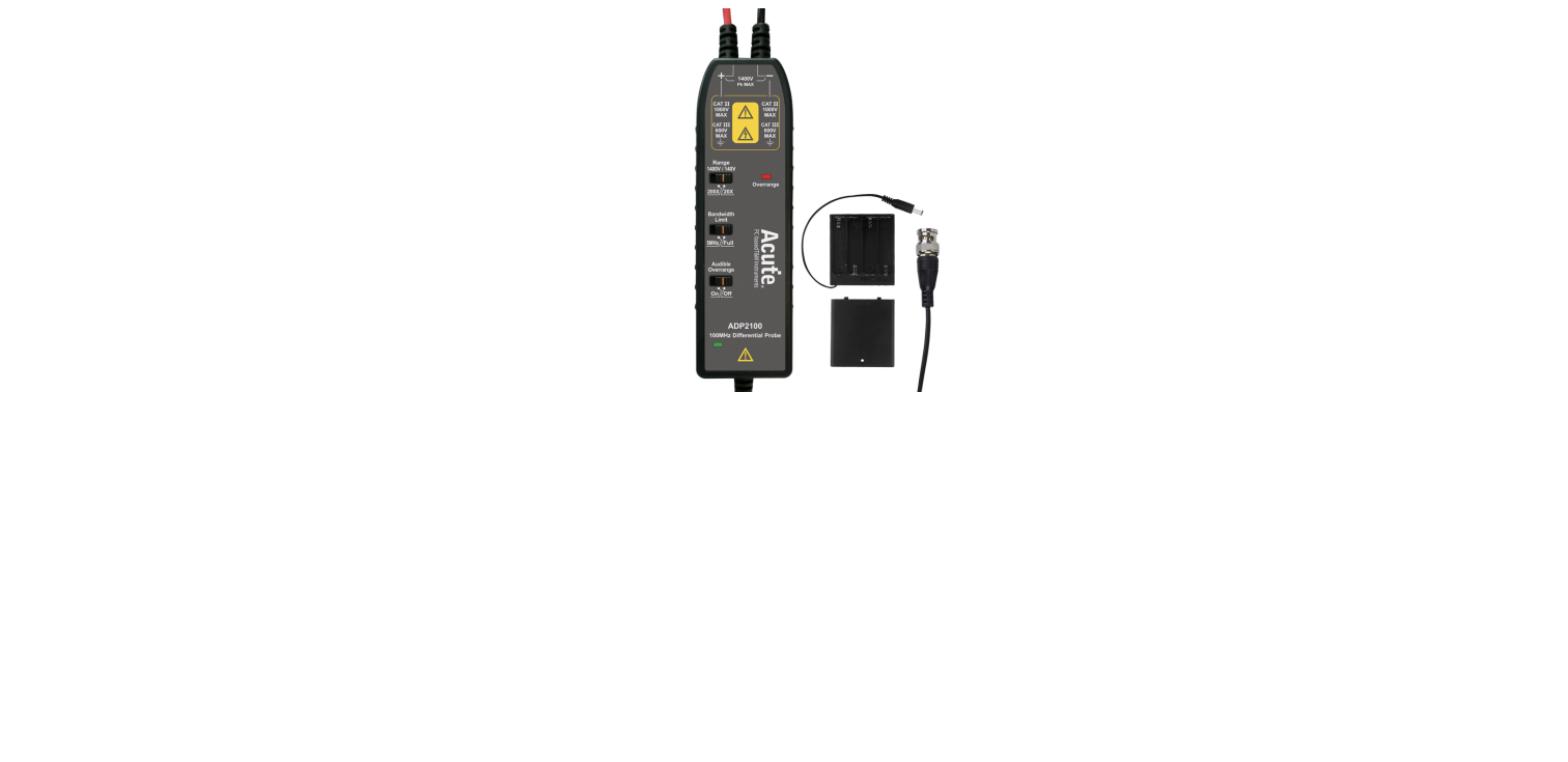
The ADP2100-B pairs the 1400V rating with 100MHz bandwidth, for faster switching events on higher-voltage rails.
Highlights
- 1400V input voltage, 100MHz bandwidth
- 20x/200x attenuation, 10Mohm/1pF input impedance
- Battery powered (AA/R6/LR6)
Key Specifications
| Spec | Value |
|---|
| Input voltage | 1400 V |
| Bandwidth | 100 MHz |
| Attenuation | 20x / 200x |
| Input impedance | 10 Mohm, 1 pF |
| Power | Battery (AA/R6/LR6) |
The USB-powered counterpart to the ADP2025-B — 1400V/25MHz isolated measurement, for continuous unattended operation.
Highlights
- 1400V input voltage, 25MHz bandwidth
- 20x/200x attenuation, 10Mohm/1pF input impedance
- USB powered
Key Specifications
| Spec | Value |
|---|
| Input voltage | 1400 V |
| Bandwidth | 25 MHz |
| Attenuation | 20x / 200x |
| Input impedance | 10 Mohm, 1 pF |
| Power | USB |
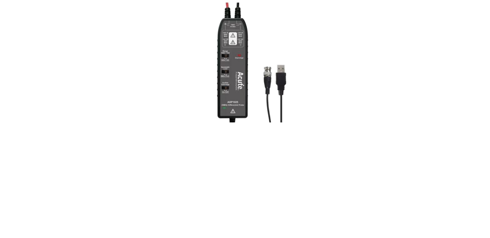
The USB-powered counterpart to the ADP1025-B — same 700V/25MHz isolated measurement spec, for continuous unattended operation.
Highlights
- 700V input voltage, 25MHz bandwidth
- 10x/100x attenuation, 10Mohm/1pF input impedance
- USB powered
Key Specifications
| Spec | Value |
|---|
| Input voltage | 700 V |
| Bandwidth | 25 MHz |
| Attenuation | 10x / 100x |
| Input impedance | 10 Mohm, 1 pF |
| Power | USB |
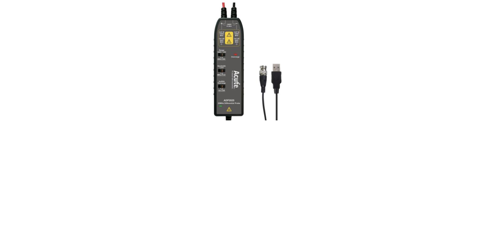
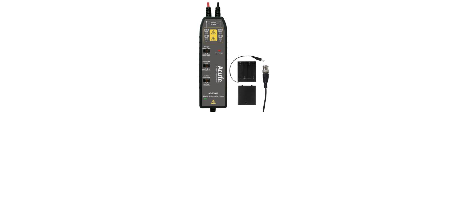
The ADP2025-B doubles the input rating to 1400V at 25MHz bandwidth, for rails the 700V line isn’t rated to touch.
Highlights
- 1400V input voltage, 25MHz bandwidth
- 20x/200x attenuation, 10Mohm/1pF input impedance
- Battery powered (AA/R6/LR6)
Key Specifications
| Spec | Value |
|---|
| Input voltage | 1400 V |
| Bandwidth | 25 MHz |
| Attenuation | 20x / 200x |
| Input impedance | 10 Mohm, 1 pF |
| Power | Battery (AA/R6/LR6) |
The ADP1025-B is an isolated differential probe rated for 700V inputs at 25MHz bandwidth, running on AA/R6/LR6 batteries for measurement points that shouldn’t be tied to a mains-referenced supply.
Highlights
- 700V input voltage, 25MHz bandwidth
- 10x/100x attenuation, 10Mohm/1pF input impedance
- Battery powered (AA/R6/LR6)
Key Specifications
| Spec | Value |
|---|
| Input voltage | 700 V |
| Bandwidth | 25 MHz |
| Attenuation | 10x / 100x |
| Input impedance | 10 Mohm, 1 pF |
| Power | Battery (AA/R6/LR6) |
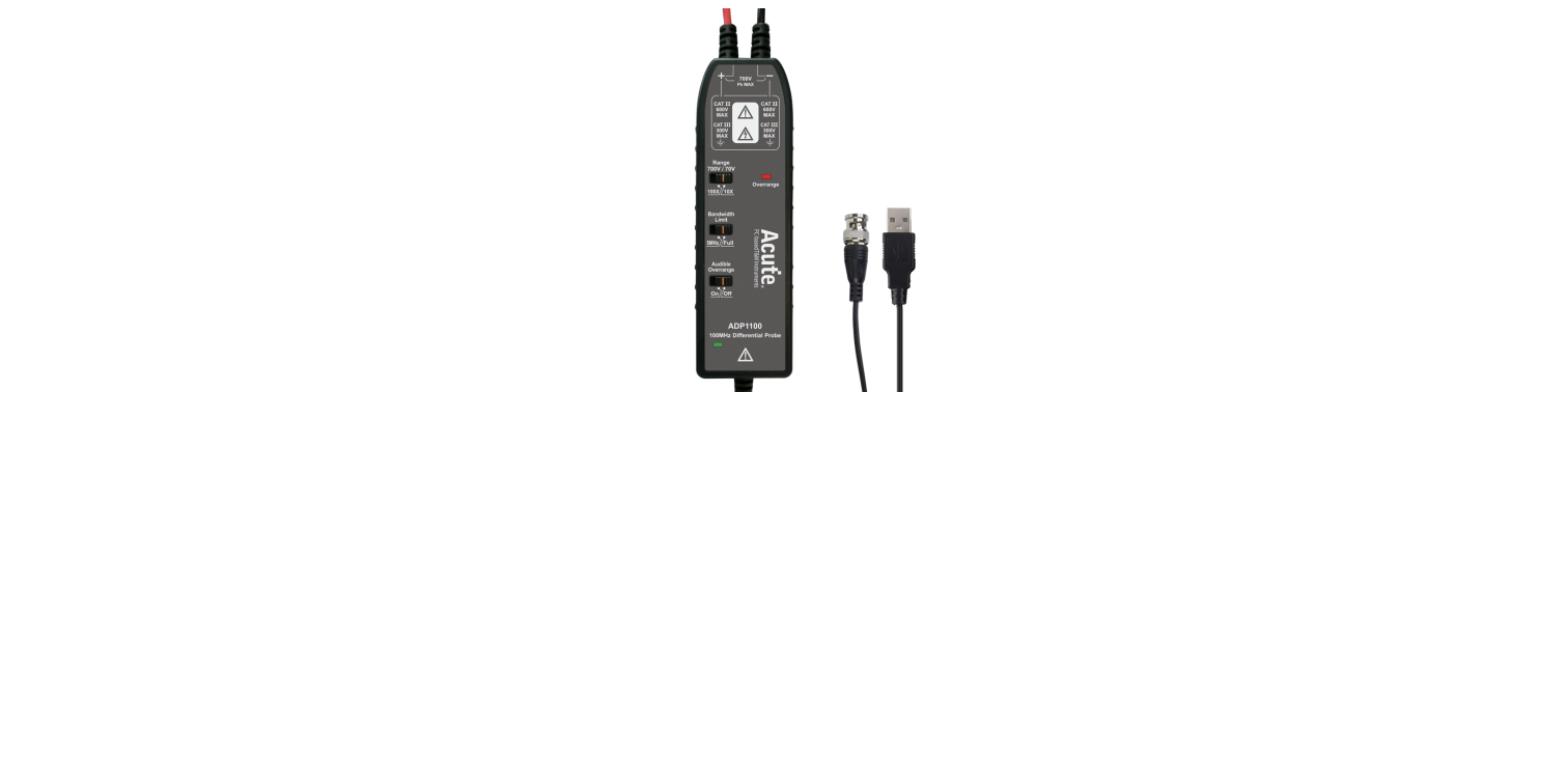
The USB-powered counterpart to the ADP1100-B — 700V/100MHz isolated measurement, for continuous unattended operation.
Highlights
- 700V input voltage, 100MHz bandwidth
- 10x/100x attenuation, 10Mohm/1pF input impedance
- USB powered
Key Specifications
| Spec | Value |
|---|
| Input voltage | 700 V |
| Bandwidth | 100 MHz |
| Attenuation | 10x / 100x |
| Input impedance | 10 Mohm, 1 pF |
| Power | USB |
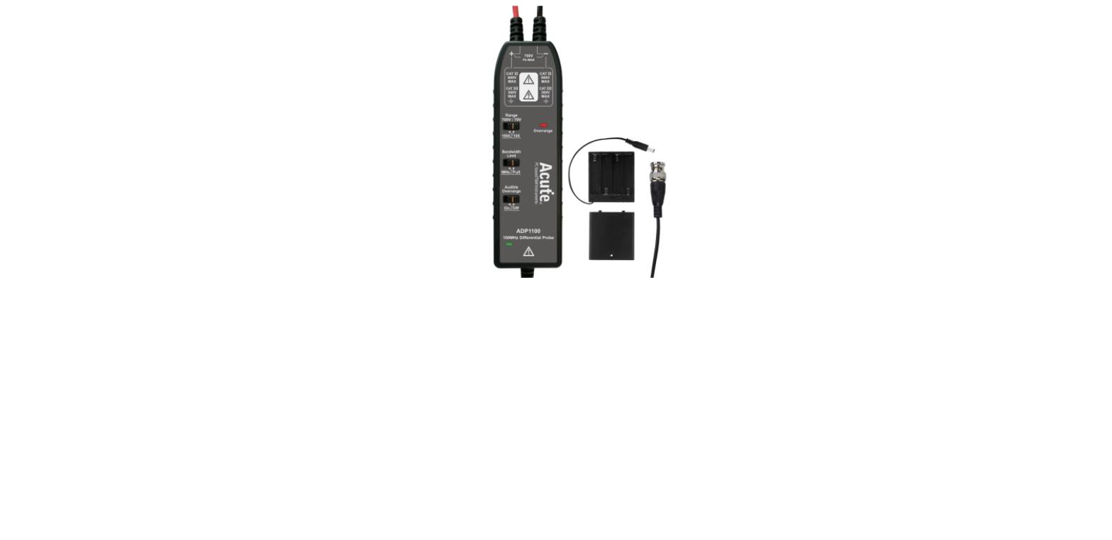
The ADP1100-B is an isolated differential probe rated for 700V inputs at 100MHz bandwidth, running on AA/R6/LR6 batteries for measurement points that shouldn’t be tied to a mains-referenced supply.
Highlights
- 700V input voltage, 100MHz bandwidth
- 10x/100x attenuation, 10Mohm/1pF input impedance
- Battery powered (AA/R6/LR6)
Key Specifications
| Spec | Value |
|---|
| Input voltage | 700 V |
| Bandwidth | 100 MHz |
| Attenuation | 10x / 100x |
| Input impedance | 10 Mohm, 1 pF |
| Power | Battery (AA/R6/LR6) |
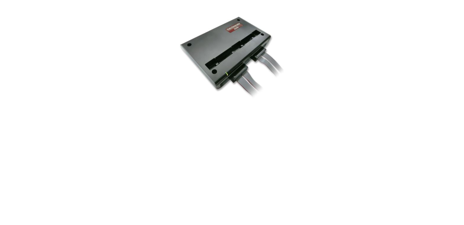
The DG4128B is DG4000’s widest configuration at 112 channels, for the largest bus-exercising jobs in the line.
Highlights
- 112 channels, 700Mbps/ch data rate
- 256Mb pattern depth per channel, 0.1V level resolution
- Successor to the discontinued DG3000
Key Specifications
| Spec | Value |
|---|
| Channels | 112 |
| Data rate | 700 Mbps / ch |
| Pattern depth | 256 Mb / ch |
| Level resolution | 0.1 V |
The DG4064B is DG4000’s 48-channel entry point, at up to 700Mbps per channel — roughly double TravelData’s data rate for wider, faster buses.
Highlights
- 48 channels, 700Mbps/ch data rate
- 256Mb pattern depth per channel, 0.1V level resolution
- Successor to the discontinued DG3000
Key Specifications
| Spec | Value |
|---|
| Channels | 48 |
| Data rate | 700 Mbps / ch |
| Pattern depth | 256 Mb / ch |
| Level resolution | 0.1 V |
The DG4096B steps up to 80 channels at the same 700Mbps/256Mb spec as the rest of the DG4000 line.
Highlights
- 80 channels, 700Mbps/ch data rate
- 256Mb pattern depth per channel, 0.1V level resolution
- Successor to the discontinued DG3000
Key Specifications
| Spec | Value |
|---|
| Channels | 80 |
| Data rate | 700 Mbps / ch |
| Pattern depth | 256 Mb / ch |
| Level resolution | 0.1 V |
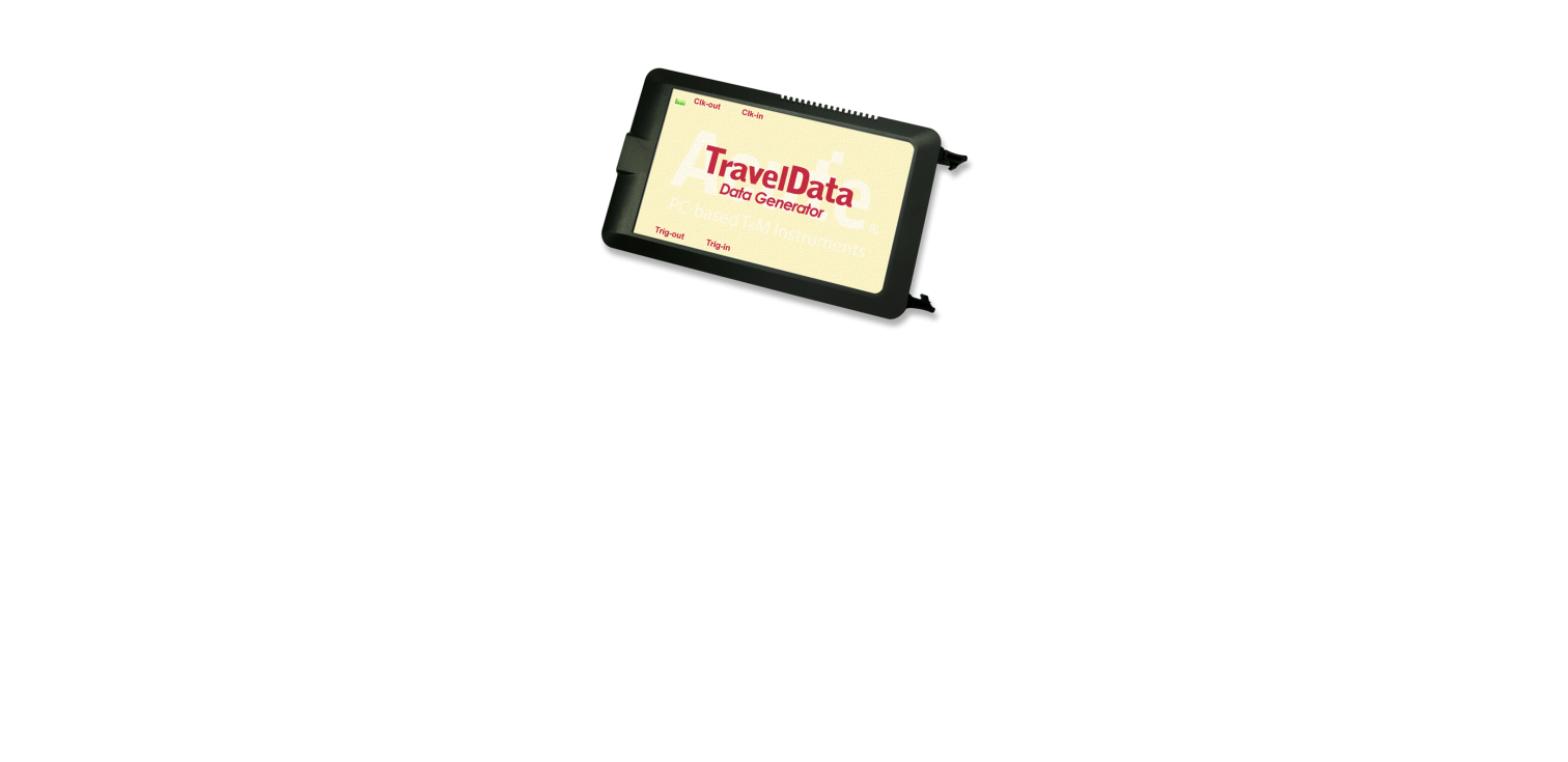
The TD3216B matches the TD3116B’s 16-channel, 200Mbps spec with 256x the pattern depth — 256Mb per channel — for long, realistic stimulus sequences rather than short loops.
Highlights
- 16 channels, 200Mbps/ch data rate
- 256Mb pattern depth per channel, 0.1V level resolution
- Default patterns for MIPI I3C, SVI3, SVID and more
Key Specifications
| Spec | Value |
|---|
| Channels | 16 |
| Data rate | 200 Mbps / ch |
| Pattern depth | 256 Mb / ch |
| Level resolution | 0.1 V |
The TD3116B is TravelData’s standard 16-channel pattern generator, with 1Mb of pattern depth per channel for driving a bus interface independently of the rest of the system.
Highlights
- 16 channels, 200Mbps/ch data rate
- 1Mb pattern depth per channel, 0.1V level resolution
- Default patterns for MIPI I3C, SVI3, SVID and more
Key Specifications
| Spec | Value |
|---|
| Channels | 16 |
| Data rate | 200 Mbps / ch |
| Pattern depth | 1 Mb / ch |
| Level resolution | 0.1 V |
The PX2816B actively drives I3C, I2C and UART traffic rather than just capturing it — including deliberately malformed frames and timing violations — to test how a target device’s error handling holds up against a bus that isn’t playing nice.
Highlights
- I3C / I2C / UART protocol support
- Error injection and compliance test mode
- Automation API for scripted regression and production test
Key Specifications
| Spec | Value |
|---|
| Protocols | I3C, I2C, UART |
| Error injection | Yes |
| Compliance test mode | Yes |
| Automation API | Yes |
The TS3124V adds electrical validation on top of the TS3124H spec — protocol-aware triggering and decode (I2C, I3C, SPI, UART and more) directly on the analog signal.
Highlights
- 4 channels, 200MHz bandwidth, 1GS/s sample rate
- 16-bit vertical resolution, electrical validation decode
Key Specifications
| Spec | Value |
|---|
| Channels | 4 |
| Bandwidth | 200 MHz |
| Sample rate | 1 GS/s |
| Vertical resolution | 16-bit |
| Electrical validation | I2C, I3C, SPI, UART, … |
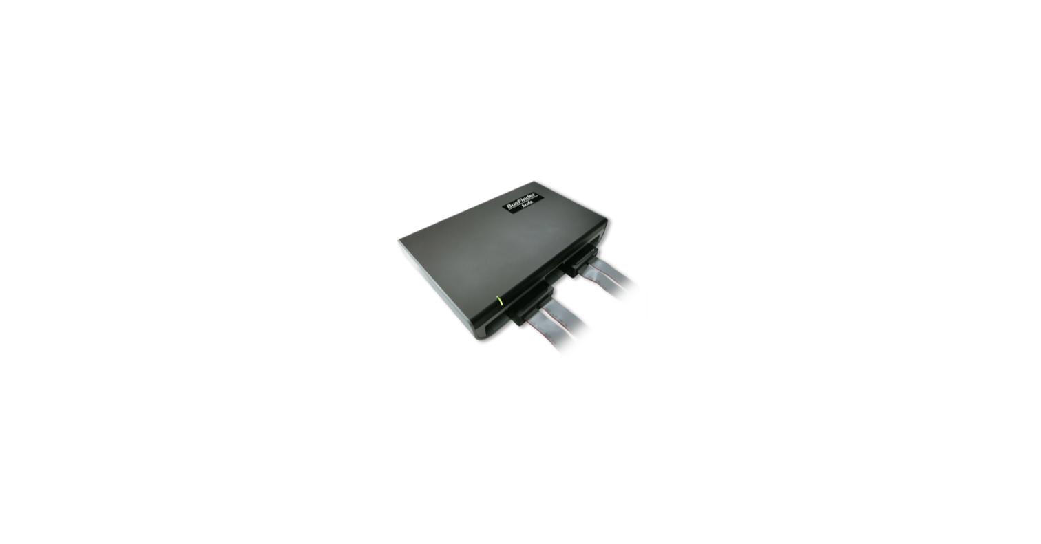
BusFinder BF7264 Pro is Acute’s flagship protocol analysis platform — a 64-channel, 4GHz capture engine extended with option modules for high-speed serial standards like MIPI D-PHY and UFS2.1 that a general-purpose logic analyzer can’t reach without external hardware.
Highlights
- 64 channels, 4GHz timing / 400MHz state analysis
- 32Gb total memory, 1Gb record length
- Protocol options: MIPI D-PHY, UFS2.1, and more
- Successor to the retired BF7264B/B+
Key Specifications
| Spec | Value |
|---|
| Channels | 64 |
| Total memory | 32 Gb |
| Timing analysis | 4 GHz |
| State analysis | 400 MHz |
| Record length | 1 Gb |
| Protocol options | MIPI D-PHY, UFS2.1, and more |
The TS3124H steps up to 16-bit vertical resolution and adds cascade support — chain multiple units together to extend channel count across boxes.
Highlights
- 4 channels, 200MHz bandwidth, 1GS/s sample rate
- 16-bit vertical resolution, cascade with other units
Key Specifications
| Spec | Value |
|---|
| Channels | 4 |
| Bandwidth | 200 MHz |
| Sample rate | 1 GS/s |
| Vertical resolution | 16-bit |
| Cascade | Yes |
The TS3124B matches the TS3124E’s 200MHz, 1GS/s, 8-bit spec in an alternate interface variant.
Highlights
- 4 channels, 200MHz bandwidth, 1GS/s sample rate
- 8-bit vertical resolution
- Alternate interface variant to TS3124E
Key Specifications
| Spec | Value |
|---|
| Channels | 4 |
| Bandwidth | 200 MHz |
| Sample rate | 1 GS/s |
| Vertical resolution | 8-bit |
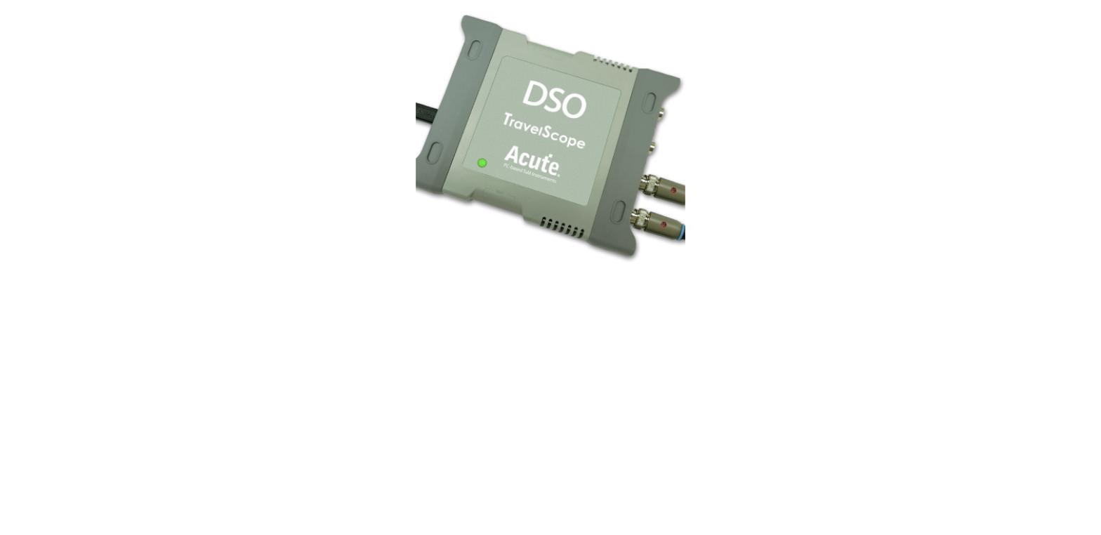
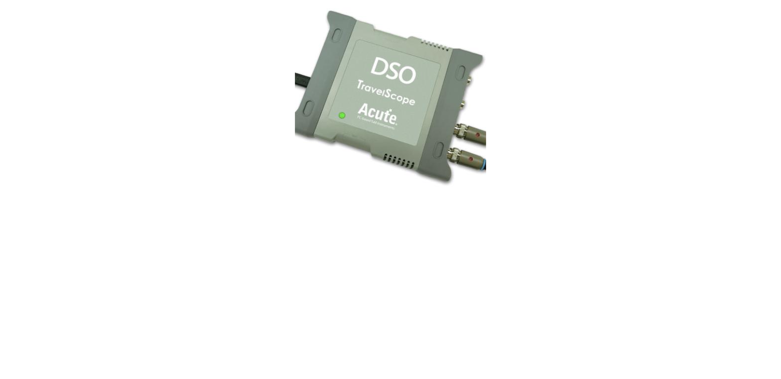
The TS3124E is TravelScope3000’s standard 4-channel, 200MHz oscilloscope — a compact, USB-hosted scope built into the same PC-based instrument family as Acute’s logic analyzers.
Highlights
- 4 channels, 200MHz bandwidth, 1GS/s sample rate
- 8-bit vertical resolution
Key Specifications
| Spec | Value |
|---|
| Channels | 4 |
| Bandwidth | 200 MHz |
| Sample rate | 1 GS/s |
| Vertical resolution | 8-bit |
The MSO3124H adds 16-bit vertical resolution and cascade support to the MSO3124 line — chain it with other Acute units to extend channel count across boxes.
Highlights
- 4 analog / 16 digital channels, 200MHz bandwidth, 1GS/s
- 16-bit vertical resolution
- Cascade with other Acute units; eSPI/SVI3/SVID support
Key Specifications
| Spec | Value |
|---|
| Analog / digital channels | 4 / 16 |
| Bandwidth | 200 MHz |
| Sample rate | 1 GS/s |
| Vertical resolution | 16-bit |
| Cascade | Yes |
| Special support | eSPI, SVI3, SVID |
The MSO3124V adds electrical validation to the MSO3124H spec — protocol-aware triggering and decode (I2C, I3C, SPI, UART and more) directly on the analog waveform, not just the digital channels.
Highlights
- 4 analog / 16 digital channels, 200MHz bandwidth, 1GS/s
- 16-bit vertical resolution, electrical validation decode
- eSPI/SVI3/SVID support
Key Specifications
| Spec | Value |
|---|
| Analog / digital channels | 4 / 16 |
| Bandwidth | 200 MHz |
| Sample rate | 1 GS/s |
| Vertical resolution | 16-bit |
| Electrical validation | I2C, I3C, SPI, UART, … |
| Special support | eSPI, SVI3, SVID |
The MSO3124B matches the MSO3124E’s 200MHz, 1GS/s, 8-bit spec in an alternate interface variant.
Highlights
- 4 analog / 16 digital channels, 200MHz bandwidth
- 1GS/s sample rate, 8-bit vertical resolution
- Alternate interface variant to MSO3124E
Key Specifications
| Spec | Value |
|---|
| Analog / digital channels | 4 / 16 |
| Bandwidth | 200 MHz |
| Sample rate | 1 GS/s |
| Vertical resolution | 8-bit |
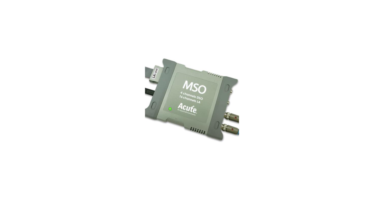
The MSO3124E steps up to real oscilloscope bandwidth — 200MHz analog with 4 channels, plus 16 digital channels at 1GS/s, still on one shared trigger.
Highlights
- 4 analog / 16 digital channels, 200MHz bandwidth
- 1GS/s sample rate, 8-bit vertical resolution
Key Specifications
| Spec | Value |
|---|
| Analog / digital channels | 4 / 16 |
| Bandwidth | 200 MHz |
| Sample rate | 1 GS/s |
| Vertical resolution | 8-bit |
The MSO2216B doubles the MSO2116 pair’s memory to 8Gb and adds eSPI, SVI3 and SVID support — useful when a longer capture window or those specific protocols are part of the debug.
Highlights
- 16 analog / 16 digital channels, 40MHz bandwidth
- 200MS/s sample rate, 8Gb total memory
- Adds eSPI, SVI3, SVID protocol support
Key Specifications
| Spec | Value |
|---|
| Analog / digital channels | 16 [same ch] |
| Bandwidth | 40 MHz |
| Sample rate | 200 MS/s |
| Total memory | 8 Gb |
| Timing analysis | 2 GHz |
| State analysis | 200 MHz |
| Special support | eSPI, SVI3, SVID |
The MSO2116E combines 16 analog and 16 digital channels behind one trigger — a compact way to see a control edge and its analog consequence in the same capture without cascading two separate instruments.
Highlights
- 16 analog / 16 digital channels, 40MHz bandwidth
- 200MS/s sample rate, 4Gb total memory
- 2GHz timing / 200MHz state analysis on the digital side
Key Specifications
| Spec | Value |
|---|
| Analog / digital channels | 16 [same ch] |
| Bandwidth | 40 MHz |
| Sample rate | 200 MS/s |
| Total memory | 4 Gb |
| Timing analysis | 2 GHz |
| State analysis | 200 MHz |
The MSO2116B matches the MSO2116E’s 16-channel, 40MHz, 4Gb spec in an alternate interface variant.
Highlights
- 16 analog / 16 digital channels, 40MHz bandwidth
- 200MS/s sample rate, 4Gb total memory
- Alternate interface variant to MSO2116E
Key Specifications
| Spec | Value |
|---|
| Analog / digital channels | 16 [same ch] |
| Bandwidth | 40 MHz |
| Sample rate | 200 MS/s |
| Total memory | 4 Gb |
| Timing analysis | 2 GHz |
| State analysis | 200 MHz |
The LA4136B matches the LA4136E’s 136-channel, 4GHz, 32Gb spec in an alternate interface variant.
Highlights
- 136 channels, 4GHz timing / 400MHz state analysis
- 32Gb total memory, 2Gb max record length
- Alternate interface variant to LA4136E
Key Specifications
| Spec | Value |
|---|
| Channels | 136 |
| Total memory | 32 Gb |
| Timing analysis | 4 GHz |
| State analysis | 400 MHz |
| Max record length | 2 Gb |
The LA4068B matches the LA4068E’s 68-channel, 4GHz, 32Gb spec in an alternate interface variant.
Highlights
- 68 channels, 4GHz timing / 400MHz state analysis
- 32Gb total memory, 2Gb max record length
- Alternate interface variant to LA4068E
Key Specifications
| Spec | Value |
|---|
| Channels | 68 |
| Total memory | 32 Gb |
| Timing analysis | 4 GHz |
| State analysis | 400 MHz |
| Max record length | 2 Gb |
The LA4136E is LA4000’s full 136-channel configuration — the widest logic analyzer in Acute’s standard line, for backplane and multi-drop bus debug where channel count is the limiting factor.
Highlights
- 136 channels, 4GHz timing / 400MHz state analysis
- 32Gb total memory, 2Gb max record length
- Successor to the discontinued LA3000+
Key Specifications
| Spec | Value |
|---|
| Channels | 136 |
| Total memory | 32 Gb |
| Timing analysis | 4 GHz |
| State analysis | 400 MHz |
| Max record length | 2 Gb |
The LA4068E is LA4000’s 68-channel entry point — the same 4GHz timing engine and 32Gb of memory as the wider 136-channel units, sized for boards that need more than TravelLogic’s 34 channels but not a full 136-wide backplane.
Highlights
- 68 channels, 4GHz timing / 400MHz state analysis
- 32Gb total memory, 2Gb max record length
- Successor to the discontinued LA3000+
Key Specifications
| Spec | Value |
|---|
| Channels | 68 |
| Total memory | 32 Gb |
| Timing analysis | 4 GHz |
| State analysis | 400 MHz |
| Max record length | 2 Gb |
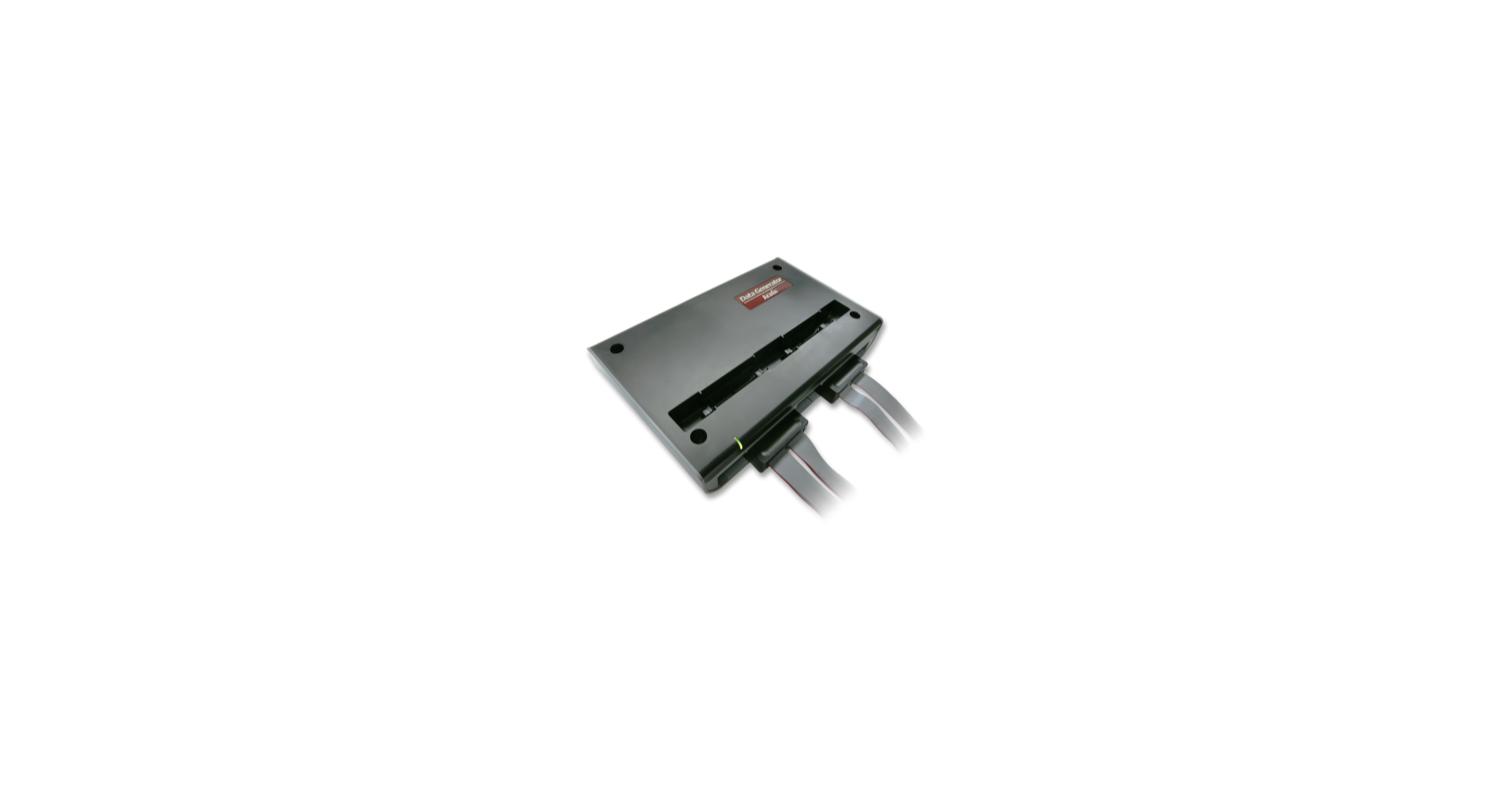
The TL4134E carries the same 34-channel, 2GHz, 4Gb spec as the TL4134B in an alternate interface variant — same capture performance, different connector/interface fit.
Highlights
- 34 channels, 2GHz timing / 250MHz state analysis
- 4Gb total memory, 512Mb max record length
- Alternate interface variant to TL4134B
Key Specifications
| Spec | Value |
|---|
| Channels | 34 |
| Total memory | 4 Gb |
| Timing analysis | 2 GHz |
| State analysis | 250 MHz |
| Max record length | 512 Mb |
The TL4234B doubles the TL4134B’s memory to 8Gb and adds explicit eSPI and SVID support — the pick when a longer capture window or those specific protocols matter more than saving on memory.
Highlights
- 34 channels, 2GHz timing / 250MHz state analysis
- 8Gb total memory, 1Gb max record length
- Adds eSPI and SVID protocol support
Key Specifications
| Spec | Value |
|---|
| Channels | 34 |
| Total memory | 8 Gb |
| Timing analysis | 2 GHz |
| State analysis | 250 MHz |
| Max record length | 1 Gb |
| Special support | eSPI, SVID |
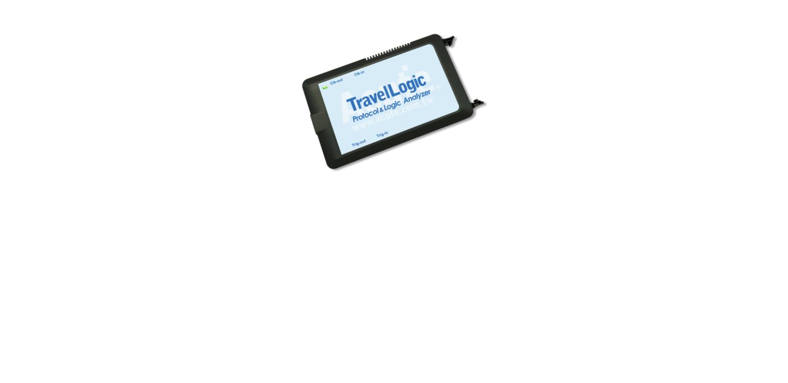
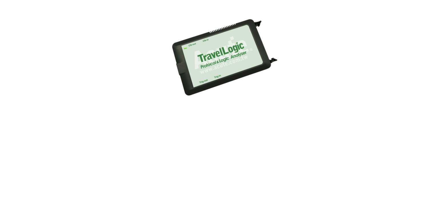
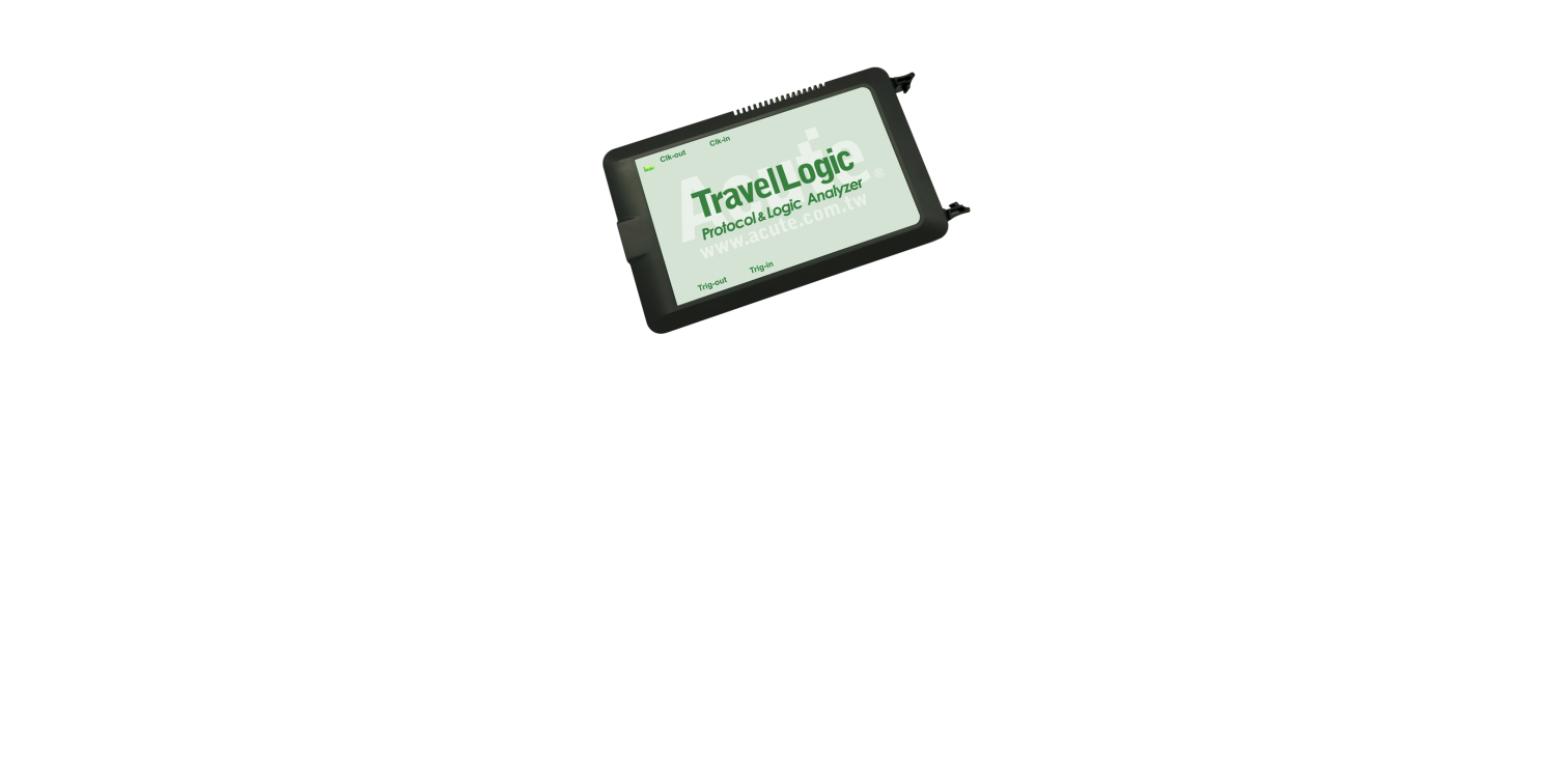
The TL4134B is TravelLogic’s standard 34-channel unit: 2GHz timing analysis and 4Gb of capture memory, enough headroom for a real board bring-up session rather than a short triggered snapshot.
Highlights
- 34 channels, 2GHz timing / 250MHz state analysis
- 4Gb total memory, 512Mb max record length
- Full protocol decode/trigger library (90+ bus decodes)
Key Specifications
| Spec | Value |
|---|
| Channels | 34 |
| Total memory | 4 Gb |
| Timing analysis | 2 GHz |
| State analysis | 250 MHz |
| Max record length | 512 Mb |
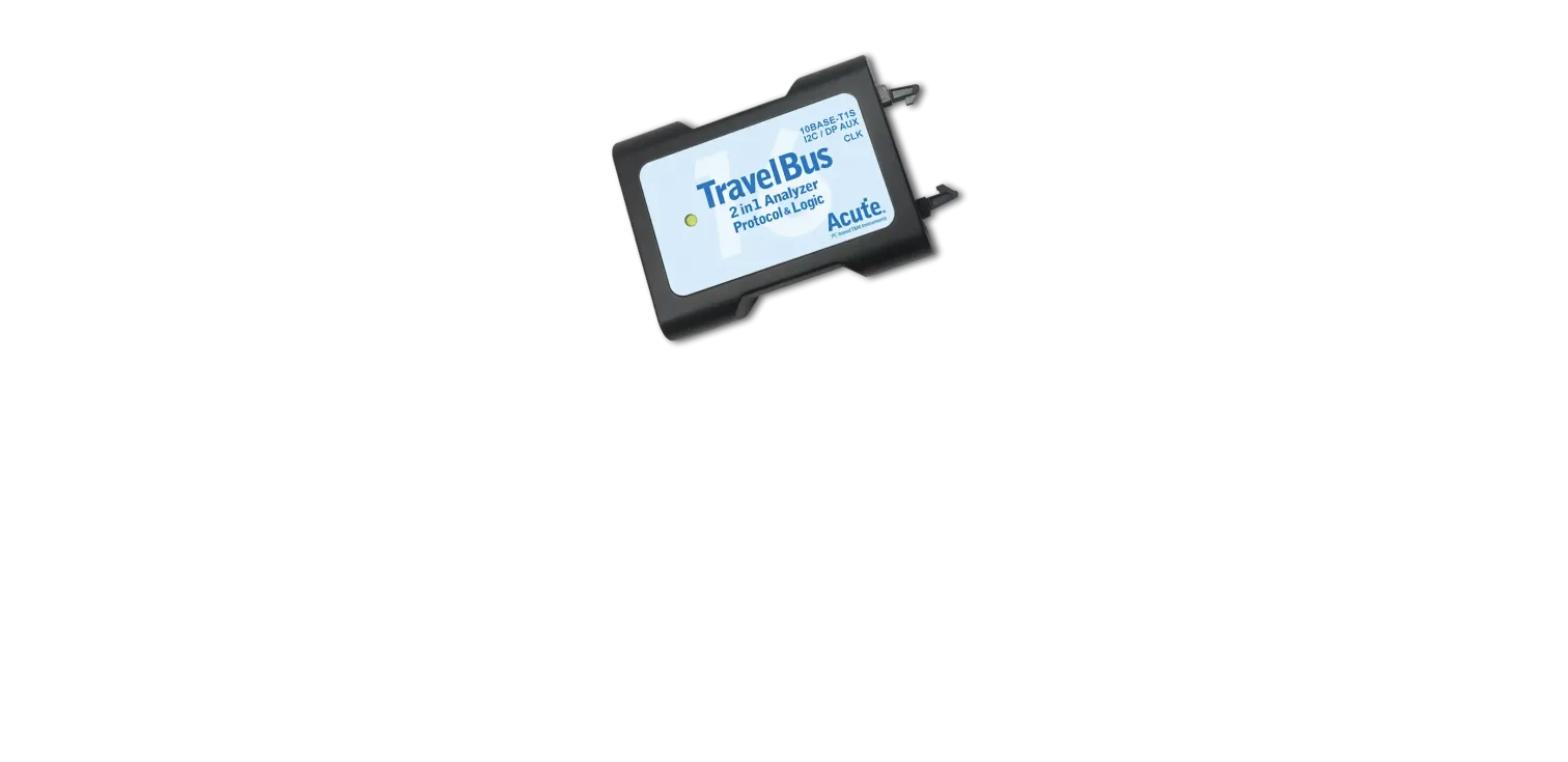
The TB3016F matches the TB3016E’s 19-channel, 800MHz spec in an alternate interface/connector configuration — pick whichever fits your existing fixture without changing capture performance.
Highlights
- 19 channels, 800MHz timing / 200MHz state analysis
- DP_Aux differential signal decode
- USB3.0-hosted, compact form factor
- Alternate interface variant to TB3016E
Key Specifications
| Spec | Value |
|---|
| Channels | 19 |
| Diff. signal decode | DP_Aux |
| Timing analysis | 800 MHz |
| State analysis | 200 MHz |
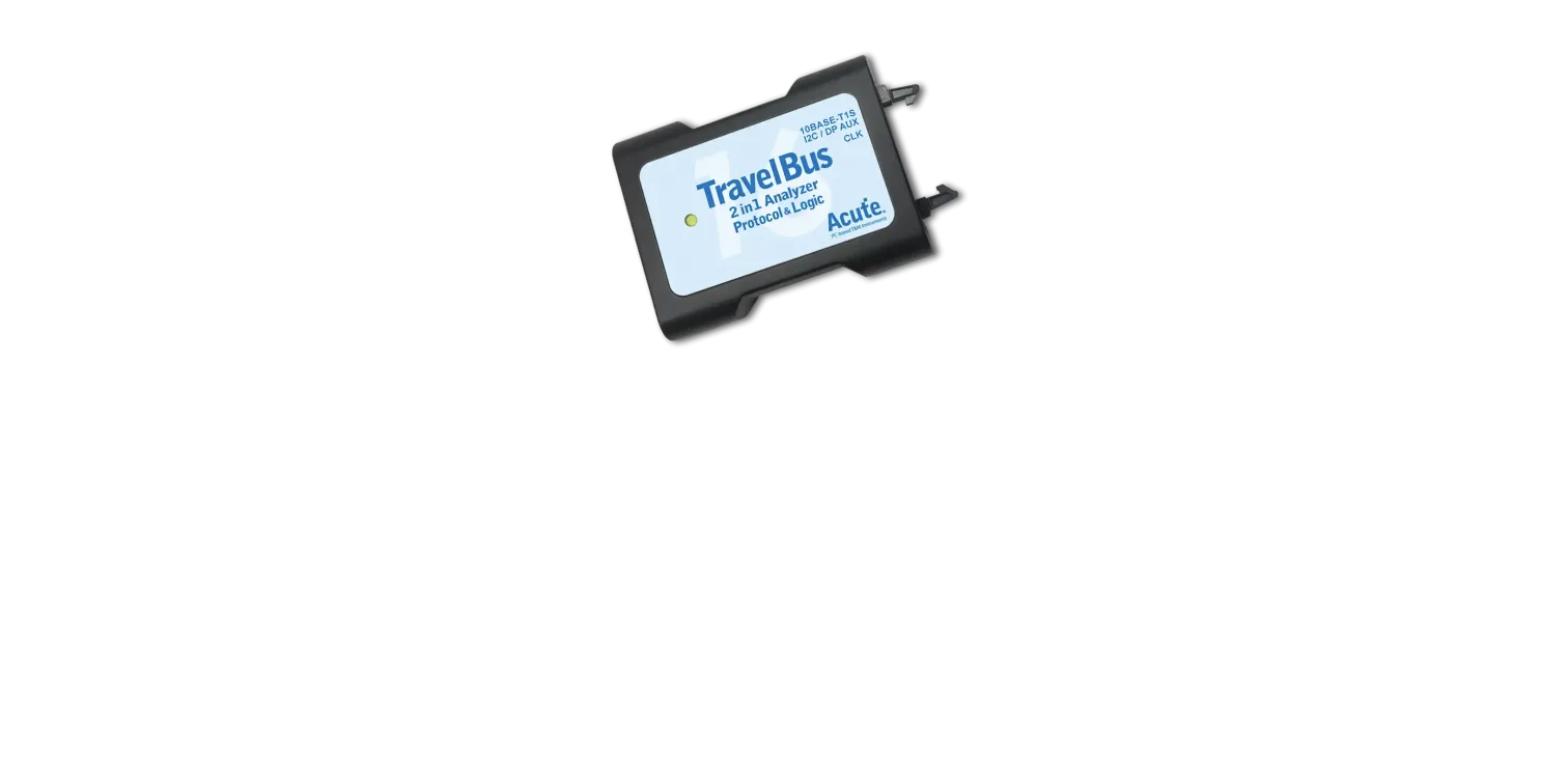
The TB3016E is TravelBus’s standard 19-channel configuration, adding DP_Aux differential decode to the same 800MHz timing engine as the rest of the line — a compact entry point into Acute’s protocol + logic analysis platform.
Highlights
- 19 channels, 800MHz timing / 200MHz state analysis
- DP_Aux differential signal decode
- USB3.0-hosted, compact form factor
- Shares Acute’s full decode/trigger library
Key Specifications
| Spec | Value |
|---|
| Channels | 19 |
| Diff. signal decode | DP_Aux |
| Timing analysis | 800 MHz |
| State analysis | 200 MHz |
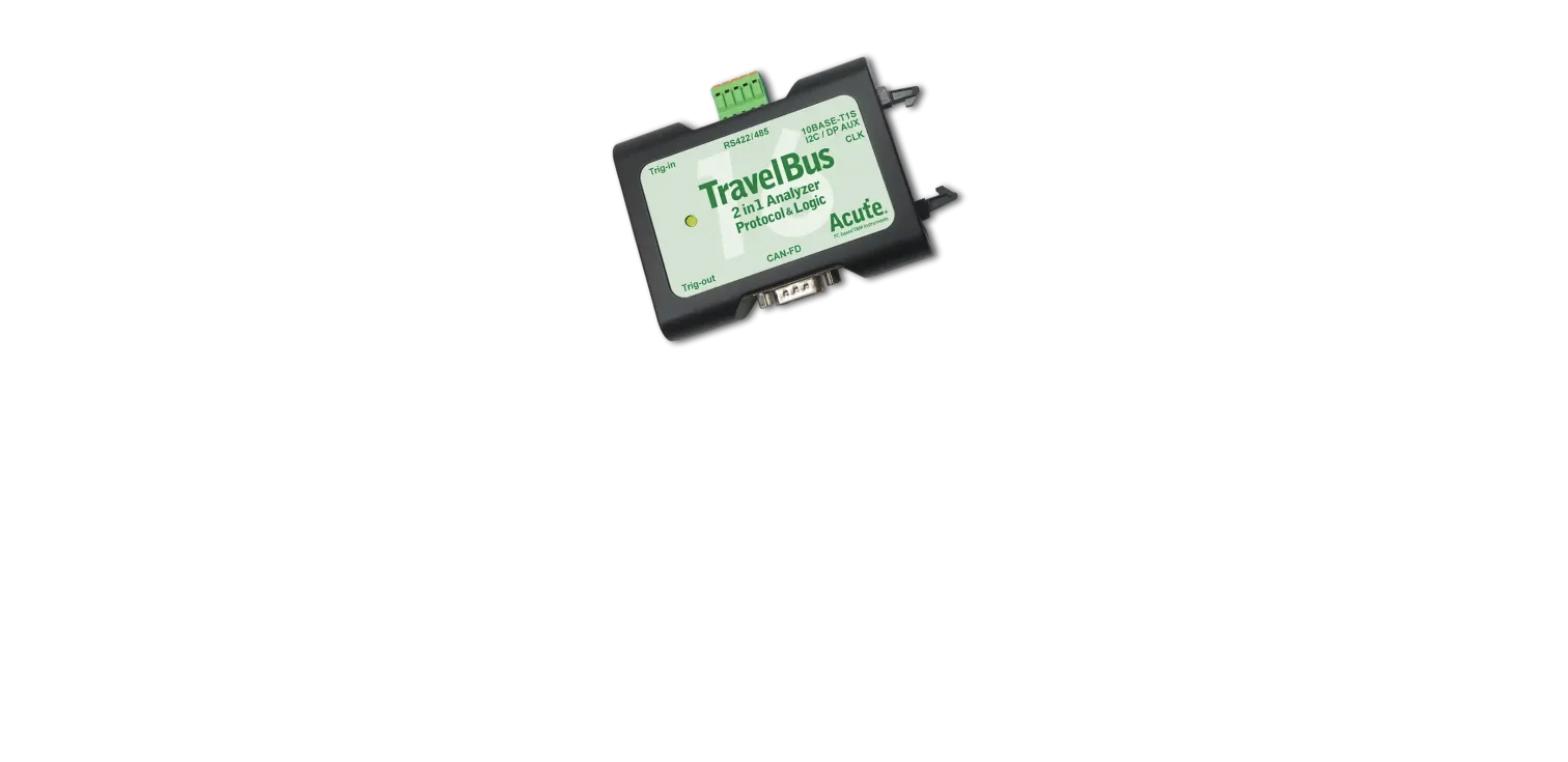
The TB3016B is the top TravelBus configuration, pairing 25 general-purpose channels with built-in differential decode for CAN2.0/CAN-FD, RS422/RS485 and DP_Aux — useful when a board mixes single-ended debug signals with a differential bus on the same header.
Highlights
- 25 channels, 800MHz timing / 200MHz state analysis
- Differential channel decode: DP_Aux, CAN2.0/CAN-FD, RS485
- USB3.0-hosted, compact 2-in-1 protocol + logic analyzer
- Shares Acute’s full decode/trigger library
Key Specifications
| Spec | Value |
|---|
| Channels | 25 |
| Diff. signal decode | DP_Aux, CAN2.0/CAN-FD, RS485 |
| Timing analysis | 800 MHz |
| State analysis | 200 MHz |
PCR Cleaning Pen – SC-N1105-KJ-IC02
Designed for cleaning contact surfaces of Pressure Conductive Silicon Rubber (PCR); removes oxide buildup for stable, reliable electrical connections and extends PCR service life.
- Replaceable silicone tip (tips sold separately)
- Reduces contact-related test errors
Key Specifications
| Spec | Value |
|---|
| Purpose | Cleans PCR (Pressure Conductive Rubber) socket contact surfaces |
| Tip | Replaceable silicone tip |
| Compatibility | PCR socket products |
Interchangeable Plug Power Adapter – ME-AD-010-005-020-002-A
Power adapter for SF600Plus, SF600Plus-G2, EM100Pro-G2/G3, and NuProg-E2; recommended for EM100Pro-G2/G3 if USB power is insufficient and causes unstable signaling.
- Input: 100-240V, 50-60Hz, 0.2A
- Output: 5V/2A
- Package includes adapter, US plug, and EU plug
Key Specifications
| Spec | Value |
|---|
| Output | 5V, 2A |
| Input | 100–240V, 50/60Hz, 0.2A |
| Plugs Included | US + EU |
| Compatible Devices | SF600Plus, SF600Plus-G2, SF700, K110, StarProg-A, EM100Pro-G2/G3, NuProg-E2 |
USB-A to USB-A Cable for NuProg-E2/NuProgPlus
Original cable included with NuProg-E2 and NuProgPlus series programmers; enables high-speed communication.
- USB-A to USB-A (M/M), 1m
- USB 3.x, up to 5 Gbps
Key Specifications
| Spec | Value |
|---|
| Length | 1m |
| USB Version | USB 3.x (up to 5Gbps) |
| Compatible Devices | NuProg-E2, NuProgPlus series (standard cable) |
USB-A to USB-C Cable for SF600Plus-G2/EM100Pro-G3
Original cable included with SF600Plus-G2 and EM100Pro-G3 programmers; connects programmer to computer with USB 2.0 high-speed transfer.
- USB-A to USB-C (M/M), 1m
- USB 2.0
Key Specifications
| Spec | Value |
|---|
| Length | 1m |
| USB Version | USB 2.0 High-Speed |
| Compatible Devices | SF600Plus-G2, EM100Pro-G3 (standard cable) |
High Pin Count Clamp – NPP-HighPinCount-Clamp
For use with the NuProgPlus Hand Press Fixture only. Designed for the DediProg M4545 programming socket; maximizes programming efficiency for high pin count devices.
- Compatible socket: M4545, package size 12x12mm-27x27mm
- Compatible fixtures: HPF-NuProgPlus-U8 or HPF-NuProgPlus
- Programs up to 4 devices simultaneously
Key Specifications
| Spec | Value |
|---|
| Purpose | Upgrades NuProgPlus Hand Press Fixture to program 4 devices at once (vs 3) |
| Package Range | 12×12mm – 27×27mm |
| Compatible With | HPF-NuProgPlus-U8 / HPF-NuProgPlus + M4545 socket |
USB-A to USB-C Cable for SF600Plus-G2U – MC-USB-AM-TypeC-1.2
Original cable included in the SF600Plus-G2U standard package; connects the programmer to a computer with a screw fastener for secure attachment.
- USB-A to USB-C (M/M), 1.2m
- USB 2.0 high-speed data transfer
Key Specifications
| Spec | Value |
|---|
| Length | 1.2m |
| USB Version | USB 2.0 |
| Feature | Screw-lock connector for secure fastening |
| Compatible Device | SF600Plus-G2U (standard cable) |
Hand Press Fixture For NuProg-E2 – HPF-NuProg-E2
Lightweight, labor-saving tool for the NuProg-E2 programmer; opens a single 5kg socket adaptor at a 1:5 force ratio.
- Dimensions: 100(L) x 50(W) x 125(H) mm
- Supports socket exterior size under 32x32mm
- 180-degree reversible install; requires DP Socket Press Plate (sold separately)
Key Specifications
| Spec | Value |
|---|
| Force Ratio | 1:5 (opens 5kg socket adaptor) |
| Dimensions | 100(L) × 50(W) × 125(H) mm |
| Feature | 180° reversible install, patented slider mechanism |
| Compatible Device | NuProg-E2 (requires DP Socket Press Plate) |
Hand Press Fixture For NuProgPlus-U16 – HPF-NuProgPlus
Labor-saving tool that opens 16 sockets at once with a 1:20 force ratio, quick-release clamps, and a patented quantitative press-down mechanism.
- Capacity up to 80kg (8 sets of socket adaptors)
- Force ratio 1:20
- Dimensions: 485(L) x 160(W) x 280(H) mm
- Compatible with NuProgPlus-U16
Key Specifications
| Spec | Value |
|---|
| Force Ratio | 1:20 (up to 80kg / 8 socket adaptor sets) |
| Dimensions | 485(L) × 160(W) × 280(H) mm |
| Construction | Steel + aluminum alloy |
| Compatible Device | NuProgPlus-U16 (opens 16 sockets at once) |
Hand Press Fixture For NuProgPlus-U8 – HPF-NuProgPlus-U8
Opens 8 sockets at once, improving IC pick-and-place efficiency; versatile clamps adapt to different socket adaptors.
- Force ratio 1:20, capacity up to 40kg (8 sets of socket adaptors)
- Dimensions: 485(L) x 160(W) x 280(H) mm
- Steel/aluminum alloy construction, quick-release clamps
Key Specifications
| Spec | Value |
|---|
| Force Ratio | 1:20 (up to 40kg / 8 socket adaptor sets) |
| Dimensions | 485(L) × 160(W) × 280(H) mm |
| Construction | Steel + aluminum alloy |
| Compatible Device | NuProgPlus-U8 (opens 8 sockets at once) |
NuProgPlus Socket Bottom Board – SF600PG2-ISP-board-NPP
Enables off-line programming for 25-series SPI flash memories via the programmer; connects using a 2×10-to-2×10 pin cable.
- 2×10 connector
- Compatible with SF600, SF600Plus, SF600Plus-G2
Key Specifications
| Spec | Value |
|---|
| Purpose | Off-line programming board for 25-series SPI flash memories |
| Connector | 2×10 to 2×10 pin cable |
| Compatible Devices | SF600, SF600Plus, SF600Plus-G2 + NuProgPlus socket |
G2U-ISO-SWD Isolation Board
Isolates target board and device when connecting via SWD using the SF600Plus-G2U, protecting both from voltage fluctuations and ESD.
- DC voltage isolation: 5000V
- Standard 20-pin SWD port, target VCC 2.5-5V
- SWD clock up to 8MHz, 3 status LEDs, 1 reset button
Key Specifications
| Spec | Value |
|---|
| Isolation | 5000V DC |
| Target Voltage | 2.5V – 5V |
| Protocol | SWD, up to 8MHz |
| Connector | 20-pin SWD |
| Compatible Device | SF600Plus-G2U |
Isolation Board for SF600 – SF600-ISO-BOARD-2
Isolation board that reduces cable interference to motherboard boot performance when SF600/SF600Plus is attached.
- Compatible with SF600, SF600Plus, SF600Plus-G2
Key Specifications
| Spec | Value |
|---|
| Purpose | Reduces cable interference to motherboard boot performance during attachment |
| Compatible Devices | SF600, SF600Plus |
G2U-ISO-JTAG Isolation Board
Isolates target board and device when connecting via JTAG using the SF600Plus-G2U, protecting both from voltage fluctuations and ESD.
- DC voltage isolation: 5000V
- Standard 20-pin JTAG port, target VCC 2.5-5V
- Clock up to 8MHz, 3 status LEDs, 1 reset button
Key Specifications
| Spec | Value |
|---|
| Isolation | 5000V DC |
| Target Voltage | 2.5V – 5V |
| Protocol | JTAG, up to 8MHz |
| Connector | 20-pin JTAG |
| Compatible Device | SF600Plus-G2U |
Isolation Board for SF100 – SF100-ISO-BOARD
Isolation board that reduces cable interference to motherboard boot performance when SF100 is attached; installed between cable and SF100 if interference occurs.
- Compatible with SF100 programmer
Key Specifications
| Spec | Value |
|---|
| Purpose | Reduces cable interference to motherboard boot performance during attachment |
| Compatible Device | SF100 |
Universal ISP Adaptor (Standard) – SPA-ISP-ADP-STD
Adapter board supplying an ICP port (20-pin) and ATE port (10-pin) with 3.3V IO for remote control.
- 20-pin ICP, 10-pin ATE, 3.3V IO
Key Specifications
| Spec | Value |
|---|
| ICP Port | 20-pin connector |
| ATE Port | 10-pin connector, 3.3V IO interface |
| Compatible Device | StarProg-A |
SF100 Universal Adaptor – ISP-UADP-127
Universal adapter for ISP programming applications, compatible with SF100 programmers and related flash modules.
- Includes BBF cable (2.54mm 2×5 female header)
- Includes 1.27mm 2×4 cable with female header
Key Specifications
| Spec | Value |
|---|
| Connectors | 2×5 (2.54mm) ISP header + 1.27mm 2×4 cable w/ female header |
| Signals | MOSI, MISO, CLK, CS, VCC, GND, I/O (Quad) |
| Compatible Device | SF100 |
BBF Testclip Dual Flash (SO16W 300mil) – BBF-2TC-16
Connects dual backup boot flash tools to two main serial flash chips on board; one SO16W test clip plus two individual clips for chip-select/hold pins.
- SO16W, 300mil pitch, dual-flash configuration
Key Specifications
| Spec | Value |
|---|
| Package | SO16W (300mil), dual-flash |
| Includes | 1 SO16W clip + 2 individual CS/HOLD clips (2nd flash) |
| Use Case | BIOS code development & serial flash repair (dual chip) |