




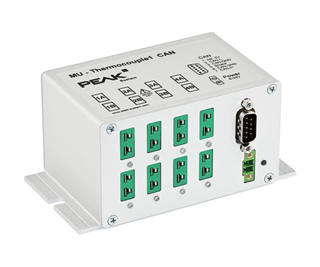
MU-Thermocouple1 CAN
Eight thermocouple inputs with on-board preprocessing and a CAN output
The MU-Thermocouple1 CAN takes eight thermocouples of one type (J, K or T, depending on the version) and sends their readings over high-speed CAN. A central microcontroller can preprocess the values before they go out on the bus.
Basic setup is done with the Thermocouple Configuration software and more advanced setups with PPCAN-Editor 2, both on a Windows PC connected to the same CAN bus.
Highlights
- 8 mini thermocouple sockets, type J, K or T depending on the version
- 4 galvanically isolated measuring modules, 2 sockets each
- On-board microcontroller for preprocessing
- Basic setup in Thermocouple Configuration, advanced setup in PPCAN-Editor 2
- Aluminium casing with flange, -40 to 85 C
Versions
- IPEH-002205-K: measuring range K, -200 to +1370 C
- IPEH-002205-J: measuring range J, -210 to +1121 C
- IPEH-002205-T: measuring range T, -200 to +400 C
Key Specifications
| Spec | Value |
|---|---|
| Order numbers | IPEH-002205-K, IPEH-002205-J, IPEH-002205-T |
| Inputs | 8 mini sockets for one thermocouple type (J, K or T) |
| Accuracy | 0.2 %; reference sensors typically 0.5 K, max. 1.0 K at +25 C |
| Resolution | 1/16 C in the CAN data |
| CAN | High-speed CAN (ISO 11898-2), CAN 2.0 A/B, 40 kbit/s to 1 Mbit/s; NXP TJA1040 transceiver |
| Isolation | Up to 500 V |
| Supply | 6 to 34 V |
| Operating temperature | -40 to 85 C |
In the Box
- MU-Thermocouple1 CAN in aluminium casing (K, J or T version as ordered)
- Mating connector for the supply (Phoenix Contact MC1,5/2-STF-3,81, 1827703)
- Thermocouple Configuration software for Windows
- PPCAN-Editor 2 for Windows
- Manual (PDF)
Thermocouple probes are not part of the delivery. Setting up the module over CAN needs a PEAK CAN interface such as the PCAN-USB FD or the PCAN-USB.
For a CAN FD output, see the MU-Thermocouple1 CAN FD.
For quantities, lead time or a quote, contact Pertech.
